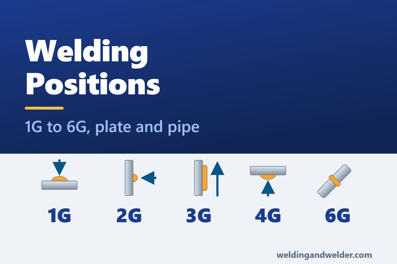
A welding position describes the orientation of the joint and weld face relative to gravity. That orientation affects how the molten pool behaves, which consumables and settings are suitable, and how easily you can reach the joint. Understanding the position helps you plan a workable setup and choose a technique that keeps the pool under control.
You will commonly see two systems used to describe these positions. AWS-style codes combine a number with G for a groove weld or F for a fillet weld. ISO 6947, widely used on British and European welding procedures, uses letter codes such as PA, PF and PH. This guide compares the main plate and pipe positions and explains what changes as you move between them.
In this guide:
Welding Positions: Quick Reference Chart
Plate Positions
| AWS | ISO 6947 | Position | What it means | Difficulty |
|---|---|---|---|---|
| 1G | PA | Flat groove | The weld is made from above along a joint in flat plate, also called downhand welding. | Usually easiest to control |
| 1F | PA | Flat fillet | The joint is rotated so the fillet sits in a 45 degree trough. | Usually easiest to control |
| 2G | PC | Horizontal groove | The plate faces are vertical and the groove runs horizontally. | Requires control of sagging |
| 2F | PB | Horizontal fillet | The fillet runs horizontally along the corner of an upright T-joint. | Pool supported by the corner |
| 3G | PF (up) / PG (down) | Vertical groove | The groove is vertical, with welding progressing up or down. | Direction and pool control matter |
| 3F | PF (up) / PG (down) | Vertical fillet | The fillet follows a vertical corner, with upward or downward progression. | Direction and pool control matter |
| 4G | PE | Overhead groove | The joint is above the welder and is welded from underneath. | Often demanding |
| 4F | PD | Overhead fillet | The fillet is made from below in a corner above the welder. | Often demanding |
Pipe Positions
| AWS | ISO 6947 | Pipe orientation | What it means | Difficulty |
|---|---|---|---|---|
| 1G | PA | Horizontal, rotated | The pipe rotates so welding can remain at the top of the joint. | Usually easiest to control |
| 2G | PC | Vertical, fixed | The pipe stands upright and the weld stays horizontal around it. | Requires control of sagging |
| 5G | PH (up) / PJ (down) | Horizontal, fixed | The fixed pipe requires welding through overhead, vertical and flat portions of the joint. | Changing orientation |
| 6G | PH-L045 (up) / PJ-L045 (down) | Fixed at 45 degrees | The inclined pipe stays fixed, testing control through a changing weld orientation. | Often demanding |
| 6GR | Inclined-pipe position; restriction defined by the test standard | 45 degrees with a restriction ring | A restricted-access pipe test, commonly used for certain structural tubular connections. | Restricted access adds difficulty |
How Welding Position Codes Work
The number and letter describe different parts of an AWS-style position code. Reading them separately makes it easier to recognise the setup before you look at the drawing or procedure.
The AWS System: a Number and a Letter
- The number identifies the position. For the main plate positions, 1 is flat, 2 horizontal, 3 vertical and 4 overhead. The 5G and 6G codes describe fixed pipe groove welds.
- The letter identifies the weld type. G means a groove weld, which may use square edges or a prepared groove. F means a fillet weld, commonly made in a T-joint, lap joint or corner joint.
- For example, 3G is a vertical groove weld and 2F is a horizontal fillet weld. Reading the number and letter together tells you both the orientation and the weld type.
The ISO 6947 System: Letter Codes
ISO 6947 uses letter codes to describe the orientation and, where relevant, the direction of welding. The table compares the common positions covered here; the joint drawing and procedure provide the remaining details.
| ISO | Position | AWS equivalent |
|---|---|---|
| PA | Flat, or downhand | 1G, 1F |
| PB | Horizontal fillet in an upright corner | 2F |
| PC | Horizontal | 2G |
| PD | Overhead fillet | 4F |
| PE | Overhead | 4G |
| PF | Vertical up | 3G or 3F upwards |
| PG | Vertical down | 3G or 3F downwards |
| PH | Upward progression around fixed horizontal pipe | 5G upwards |
| PJ | Downward progression around fixed horizontal pipe | 5G downwards |
| PH-L045 / PJ-L045 | Fixed pipe at 45 degrees: upwards / downwards. Formerly H-L045 / J-L045 | 6G, with the direction specified |
PF and PG are worth learning together because they distinguish the direction of vertical welding. On plate, 3G describes a vertical groove weld, while PF means welding upwards and PG means welding downwards. The direction changes how the pool is supported and how you control fusion, so it is a choice to make with the process and procedure in mind.
Plate Codes and Pipe Codes Are Not the Same
The same number can look quite different on plate and pipe. In 1G, a plate joint lies flat, while a horizontal pipe is rotated so welding takes place at the top. In 2G, the groove runs horizontally across upright plate or around an upright pipe. The additional 5G and 6G pipe positions describe fixed joints where the weld orientation changes as you move around the circumference.
Flat Position: 1G, 1F and PA
In the flat position, you weld from above and the joint supports the molten pool. This usually makes the pool easier to manage and allows higher deposition rates than vertical or overhead welding. Where the material and joint allow it, you can take advantage of larger consumables or higher settings without fighting the same tendency for metal to sag or fall.
- Use the flat position where it suits the job. Turning or securing the work so you can weld from above often makes access and pool control easier, which can reduce welding time and rework.
- Keep the technique suited to the process. Use a steady travel speed and the recommended arc length and travel angle. A straight run or a controlled weave may be appropriate, depending on the joint and procedure.
- Watch the toes and bead profile. Excessive current or travel speed can contribute to undercut, while poor fusion or an overly convex bead can have several causes. Check the balance of current, travel speed and deposited metal rather than assuming more heat will fix it.
- Take advantage of suitable flat-position consumables. This includes higher-deposition products that are restricted to flat welding or horizontal fillets, as well as products rated for wider positional use.
Horizontal Position: 2G, 2F, PC and PB
A horizontal groove runs across a vertical face, so gravity draws the molten pool towards its lower edge. That makes the upper and lower toes behave differently: the upper edge can develop undercut, while excess metal can collect below and form overlap. Keeping the pool manageable helps you fuse both sides of the joint evenly.
- Direct the arc so both sides fuse properly. A suitable work angle helps control the upper toe without allowing the pool to collect excessively at the lower edge. Keep the arc length and pool size appropriate to the process.
- Consider a smaller consumable where it improves control. The aim is a manageable pool; changing wire or electrode diameter is one option alongside the permitted settings and travel speed.
- Build up thicker joints with controlled runs. Narrow stringer beads, often placed from the lower side upwards, can be easier to manage than a wide weave in a horizontal groove.
- A 2F fillet has more support beneath the pool. The corner of the T-joint helps hold the metal in place, although you still need to control the leg lengths and achieve fusion into both faces.
Vertical Position: 3G, 3F, PF and PG
With a vertical joint, you need to control the pool as gravity draws it downwards. Welding uphill and downhill manage that movement in different ways, which is why the travel direction matters as much as the position code.
Vertical Up (PF)
- Work from the bottom upwards, using the solidified weld beneath the pool to help support each new section.
- Uphill welding is commonly chosen for structural work and thicker sections, including work around 6 mm and above, because it allows controlled fusion and filling. The suitable direction still depends on the process and joint, rather than a fixed thickness cut-off.
- Use the movement recommended for the process and consumable, with a controlled weave only where permitted. Whipping is suitable for some electrodes but should not be applied automatically to every vertical weld.
Vertical Down (PG)
- Downhill travel can help limit heat input on thin sheet when the process and settings are suitable. The faster travel makes it important to check that the arc is still achieving fusion.
- It is also used in established pipeline procedures, including those using suitable cellulosic electrodes. These applications are not limited to thin material.
- Keep control of the relationship between the arc and the pool. If molten metal or slag runs ahead and shields the joint from the arc, lack of fusion or slag inclusions can result.
- Confirm that downhill progression is permitted before choosing it. Structural and other specified work may restrict the direction or require a procedure qualified for it.
Overhead Position: 4G, 4F, PE and PD
Overhead welding places the joint above you, with the weld made from underneath. The pool needs careful control because gravity pulls it away from the joint, and falling spatter makes protection and body position especially important. It is often worth repositioning the work where that can be done safely and efficiently.
- Consider repositioning the work first. Moving the joint into a flat position can improve access and reduce exposure to falling spatter, provided the handling can be done safely and is worthwhile for the job.
- Use settings that keep the pool manageable. Lower current than a comparable flat weld may help, but enough heat is still needed for fusion. Keep the arc length within the consumable or process recommendations.
- Use suitable diameters and controlled runs. Smaller consumables and narrow stringer beads are often easier to manage overhead than a large pool, subject to the welding procedure.
- Choose protection for falling spatter. Suitable welding clothing, gloves and head and neck protection should cover exposed areas and avoid openings where hot metal can collect.
Fillet Weld Positions: 1F to 4F
The familiar 1F to 4F codes describe the flat, horizontal, vertical and overhead fillet positions. A fillet joins the faces meeting at a corner, and its size is described by dimensions such as leg length and throat. The examples below cover the main plate positions; pipe fillet positions such as 5F also exist.
- 1F is the flat fillet. Rotating a typical T-joint so its faces form a 45 degree trough gives the pool support from both sides.
- 2F (ISO PB) is the horizontal fillet on an upright T-joint, a familiar setup in general fabrication.
- 3F is the vertical fillet, with PF used for upward progression and PG for downward progression.
- 4F (ISO PD) is the overhead fillet, made from beneath the joint.
- Check the specified fillet dimensions. A convex bead or unequal legs can make a weld look larger without providing the required effective throat. Use an appropriate gauge to assess the size and profile.
Pipe Welding Positions: 1G, 2G, 5G and 6G
On pipework, the important starting point is whether the pipe can turn. A rolled joint can keep the welding in one position, while a fixed joint requires you to follow the changing orientation around the pipe.
1G Pipe: Rolled (PA)
As the pipe turns, you keep the arc near the top of the joint and weld in the flat position. This can make access easier and improve consistency and productivity, which is why workshops use pipe rotators. Before planning a rolled weld, check that the assembly can be supported and rotated safely and that the procedure allows it.
2G Pipe: Vertical, Fixed (PC)
Here the pipe stands upright and remains fixed, so the weld runs horizontally around its circumference. The pool has the same tendency to sag as a 2G plate weld, and narrow runs with a suitable torch or electrode angle can help control it. Unlike 5G, the weld stays horizontal as you work around the joint.
5G Pipe: Horizontal, Fixed (PH or PJ)
A fixed horizontal pipe takes you through overhead, vertical and flat welding around the same joint. At 6 o’clock you work underneath the pipe, at 3 and 9 o’clock the travel is vertical, and at 12 o’clock you reach the flat position. As you move between them, adjust your body position and torch angle while keeping within the procedure’s settings.
For a complete fixed-pipe joint, ISO 6947 uses PH for upward progression and PJ for downward progression. Downhill welding is used in suitable pipeline procedures as well as some thinner-wall applications; its suitability depends on the process, consumable and joint requirements.
6G Pipe: Fixed at 45 Degrees
A 6G test is widely used because an inclined, fixed pipe demands control through a changing weld orientation. The pipe axis is set at 45 degrees and the pipe does not rotate, so access and torch angle change as you work around it. ISO 6947:2019 uses PH-L045 for upward progression and PJ-L045 for downward progression; older documents commonly use H-L045 and J-L045. The test can provide broad qualification coverage, but its actual range still comes from the applicable standard and certificate.
6GR adds restricted access, commonly using a ring close to the test joint. It is associated with structural tubular qualification, including certain T-, Y- and K-connections, where the welder must demonstrate that they can make the weld despite an obstruction.
Which Welding Process Suits Which Position
Several processes can be used in all positions, provided the consumable and setup are suitable. With MIG, the transfer mode is particularly important because it affects the size and fluidity of the pool. The wire, shielding gas and machine settings work together to establish that mode.
| Process | Positions | Notes |
|---|---|---|
| MMA (stick) | All positions with suitable electrodes | Check the product’s position and progression limits. High-deposition iron-powder types may be restricted to flat welding and horizontal fillets. |
| MIG, dip (short circuit) | Suitable for all positions with the right setup | A relatively small pool helps positional control, but settings and technique must still achieve adequate fusion. |
| MIG, spray transfer | Generally flat welding and horizontal fillets | Conventional spray transfer produces a fluid pool that is difficult to support in vertical and overhead work. |
| MIG, pulsed | Suitable for all positions with the right programme | Pulsing combines droplet transfer with a lower background current, helping control the pool. Check the wire, gas and programme together. |
| Flux-cored (FCAW) | Depends on the wire | Suitable all-position wires can work well vertically and overhead. Confirm the product’s diameter and travel-direction limits. |
| TIG | All positions | Offers close control and is commonly used for pipe roots in 5G and 6G. It can also be used for fill and cap where the procedure and productivity needs suit it. |
| Submerged arc | Usually flat welding and horizontal fillets | The granular flux and weld pool need support, which limits the practical position range. |
Some pipe procedures combine processes to make use of their different strengths: TIG provides control for the root, while MMA or flux-cored welding can offer a higher deposition rate for the fill and cap.
Consumables Rated for All Positions
Check the consumable’s position rating before setting up the machine. A product designed for high deposition in the flat position may not be suitable for vertical or overhead work. The classification gives useful information, while the manufacturer’s data confirms the permitted positions, travel directions and operating range.
Flux-Cored Wires: the Second Digit
For a carbon-steel flux-cored classification such as E71T-1, the second digit identifies the position category. That makes it a useful first check when comparing otherwise suitable wires.
- E71T identifies the all-position category in this classification format. Check the specific product’s limits for diameter and vertical travel direction.
- E70T identifies a wire intended for flat welding and horizontal fillets. These products may offer high deposition rates within their permitted positions.
- Stainless flux-cored and metal-cored wires use different classification formats. Check their own position designations and product data rather than assuming the same digit appears in the same place.
Browse flux-cored steel MIG wire or the flux-cored stainless range, then check the position rating and operating data for the individual product.
MMA Electrodes: the Third Digit
In a four-digit electrode classification such as E7018, the third digit identifies the position category. A 1 denotes an all-position classification, while a 2 restricts use to flat welding and horizontal fillets. The product data still matters, particularly for vertical travel direction.
- E6013 and E7018 are familiar all-position classifications, but they have different characteristics and applications. Many E7018 products exclude vertical-down use, so the position digit is not the whole instruction.
- E7024 is a high-deposition iron-powder electrode for flat welding and horizontal fillets. It is not intended for vertical or overhead joints.
- For vertical-up E7018 work, a smaller electrode can help control the pool. For example, a 2.5 mm rod may suit a job where 3.2 mm would be used flat, but use the manufacturer’s range and the procedure to choose the size and bead technique.
Our MMA stick electrodes range lets you compare products for the material and position you need to weld.
Wire and Rod Diameter
| Position | Typical MIG wire | Why |
|---|---|---|
| Flat and horizontal | 1.0 to 1.2 mm | Examples for suitable work at higher deposition rates; the joint and transfer mode still limit pool size. |
| Vertical and overhead | 0.8 to 1.0 mm | Examples where a smaller wire helps low-current control. Larger wires can also be suitable with the right process and programme. |
| Thin sheet, any position | 0.6 to 0.8 mm | Smaller wire can help control heat input on thin material. Match the diameter to the material and transfer mode. |
You can browse MIG welding wire and TIG filler rods by material and diameter, then confirm the size against the joint, process and required operating range.
Setting Up for Out-of-Position Work
First, Try Not to Weld Out of Position at All
Before working around an awkward position, consider whether the assembly can be moved. Rotating a suitable pipe changes a fixed 5G joint into a rolled 1G weld, which may make the welding quicker and easier to control. Weigh that benefit against the handling time, lifting arrangements and space needed to turn the work safely.
- Pipe stands and rollers support the pipe, with suitable roller arrangements allowing it to turn for a rolled weld.
- Pipe alignment clamps help hold alignment while you set the root gap and tack. Consistent fit-up matters in every position and becomes harder to manage when access changes around a fixed pipe.
- Magnetic positioners can help hold compatible plate at the required angle, making it easier to arrange a joint for flat welding.
- Ceramic backing tape supports and shapes the root in suitable joints. Use a product approved for the process and position; sound single-sided roots are also possible with other qualified techniques.
Machine Settings
- Adjust settings for the position and consumable. For some MMA work, reducing current by roughly 10 to 15 percent from comparable flat settings is a useful starting point. It is not a general rule for every process, and the final settings must still provide fusion.
- Pulsed MIG can make positional pool control easier. Synergic controls simplify linked settings, but the word “synergic” alone does not mean the machine has a suitable pulse mode or positional programme.
- Match the shielding gas to the wire and transfer mode. Changing the CO2 content changes arc behaviour, but more CO2 is not a general solution for positional work. Use the mixture specified for the process, material and machine programme.
- Browse welding machines with the required position, process and consumables in mind when choosing a set.
PPE For Out of Position Welds
- Choose welding clothing rated for the spatter exposure. For overhead work, a suitable cape sleeve, skull cap and gauntlets can help protect the shoulders, head and arms. Arrange collars, cuffs and glove overlaps so falling metal cannot enter or become trapped; leather is one option, alongside suitably rated flame-resistant garments.
- Keep your head out of the fume plume and position fume extraction to capture fume effectively as you move. Exposure depends on the task and airflow, so assess it in every position and add suitable respiratory protection where required.
- Browse welding clothing, the wider safety equipment range and fume extraction to suit the task and its assessed risks.
Common Defects by Position
| Position | Typical defects | Cause | Fix |
|---|---|---|---|
| Flat (1G, 1F) | Undercut at the toes, excess convexity, porosity | Possible causes include mismatched current and travel speed, excessive deposition, contamination or poor shielding | Identify the defect first, then check settings, travel, cleanliness, shielding and consumable condition |
| Horizontal (2G, 2F) | Undercut along the top toe, sag and overlap along the bottom toe | Gravity draws metal towards the lower side; angle and bead placement also affect fusion | Use a manageable pool and appropriate work angle, with controlled runs that fuse both sides |
| Vertical up (3G, PF) | Excess convexity, trapped slag between runs, overheating | Poor balance of deposition and travel, wide weaving, inadequate cleaning or unsuitable heat input | Review settings and bead sequence, use the consumable’s recommended movement, and clean between runs |
| Vertical down (3G, PG) | Lack of fusion, slag inclusion, shallow penetration | The pool or slag can run ahead of the arc and prevent fusion | Control the arc at the leading edge of the pool and follow a suitable downhill procedure |
| Overhead (4G, 4F) | Sagging and dripping, incomplete fusion, porosity | An oversized pool, unsuitable heat input, contamination or disturbed shielding | Control pool size without losing fusion, use suitable runs, and check shielding and cleanliness |
| Pipe 5G and 6G | Lack of penetration at the root, defects at start and stop points | Changing access and orientation, inconsistent fit-up or poorly prepared restarts | Maintain fit-up and torch control, prepare restarts as specified, and keep settings within the procedure |
Safety Risks by Position
Arc radiation, fume and burns need attention in every position. What changes is your exposure to them: where the spatter can fall, whether your head is in the fume plume, and how comfortably you can hold the working position.
| Position | The risk that changes | What to do about it |
|---|---|---|
| Flat | Leaning over the joint can put your head in the rising fume plume | Use effective fume control and keep your head out of the plume |
| Horizontal | Awkward reach and unstable work can cause strain or movement during welding | Secure the work and set a comfortable working height |
| Vertical | Slag and spatter can fall down the body; sustained reaching can cause fatigue | Cover openings, wear trousers over boots, avoid turn-ups and use suitable work-rest arrangements |
| Overhead | Falling metal can enter cuffs, collars or ears; looking upwards can strain the neck | Use suitable welding clothing and head and neck protection; arrange overlaps to shed spatter and improve the working position where possible |
| Pipe and confined spaces | Fume, oxygen displacement, restricted access and difficult escape | Avoid entry where possible. Essential entry needs isolation, atmospheric testing, ventilation, suitable breathing protection where required, and a planned rescue system |
Welder Qualification Ranges
A welder qualification may cover a range of production positions beyond the test position. The range is defined by the qualification standard rather than a simple ranking of easier and harder welds. Read the position coverage together with the other limits on the certificate.
- In the UK and Europe, the BS EN ISO 9606 series is widely used for welder qualification. It uses ISO 6947 position designations, with the relevant part selected for the material.
- For many pressure-equipment projects, including work in the US and internationally, ASME Section IX provides qualification rules using the familiar 1G to 6G position designations.
- A 6G test can provide broad positional coverage. Check the applicable qualification table and the direction of progression, rather than assuming that every plate, pipe, groove and fillet application is included.
- Position is only part of the qualification range. Depending on the standard, the limits can include process, filler-metal grouping, deposited thickness, pipe diameter, backing and travel direction. A stainless test does not automatically exclude carbon-steel work, and a 50 mm pipe test may cover 300 mm pipe: check the recorded range and the relevant rules.
- Keep qualifications current. Continuity confirmation and revalidation requirements vary with the standard and certification route. Check the dates and records, especially after a break from using the process.
Check the certificate against the edition of the qualification standard and the specification that apply to the job. The position code is a useful starting point, but it does not show the full scope of approval on its own.
Welding Positions FAQ
What are the four main welding positions?
The main positions are flat, horizontal, vertical and overhead. On plate, these use the familiar 1G to 4G groove codes and 1F to 4F fillet codes. ISO 6947 uses PA for flat, PC and PB for the common horizontal groove and fillet positions, PF or PG for vertical progression, and PE and PD for the common overhead positions. Fixed pipe also uses 5G and 6G, where the weld orientation changes around the joint.
What is the 6G welding position?
In 6G, the pipe axis is fixed at 45 degrees and the pipe cannot rotate. The welder follows the joint around the circumference, adjusting to the changing orientation and access. ISO 6947:2019 uses PH-L045 for upward progression and PJ-L045 for downward progression; H-L045 and J-L045 are older designations still seen in documents. A 6G test can give broad position coverage, subject to the qualification rules.
Which welding position is the hardest?
Overhead welding is often demanding because the pool needs close control and spatter falls towards the welder. A fixed 6G pipe test adds changing access and orientation around an inclined joint. There is no universal difficulty ranking, though: the process, material, joint preparation and available access all affect how challenging a weld is.
What is the difference between 3G and PF?
For a vertical plate groove, 3G is the AWS-style position code and does not by itself state the travel direction. ISO 6947 uses PF for welding upwards and PG for welding downwards. The procedure supplies the required direction, consumable and technique.
What is the difference between a G and an F welding position?
G identifies a groove weld, which can be made between square or prepared edges. F identifies a fillet weld, commonly used in T-joints, lap joints and corner joints. For the main plate positions, the numbers 1 to 4 identify flat, horizontal, vertical and overhead welding in either group.
Can you MIG weld in all positions?
MIG can be used in all positions with a suitable transfer mode and setup. Short-circuit and pulsed modes can help control the pool, while conventional spray transfer is generally used for flat welding and horizontal fillets. Flux-cored welding also depends on the wire’s position rating and operating range. Check the wire, gas, diameter and settings together rather than relying on the machine label alone.
Does a 6G welding test qualify you for all positions?
A 6G pipe test can qualify a broad range of production positions, but it is not approval for every welding task. The applicable standard defines the range, including any limits on progression, weld type, process, filler grouping, thickness, diameter and backing. Check the certificate against the job, including whether separate fillet coverage is needed.
Plan the position alongside the process, consumables and access. Together they determine how you control the pool, how efficiently you can work and which problems need particular attention. Where the assembly can be repositioned safely and the procedure permits it, welding flat is often a useful way to simplify the job.
To match the consumables to the work, browse MIG welding wire, TIG filler rods and MMA stick electrodes, which can be filtered by material type. If you need help choosing a suitable product, ask us with the material, thickness, process and welding position.