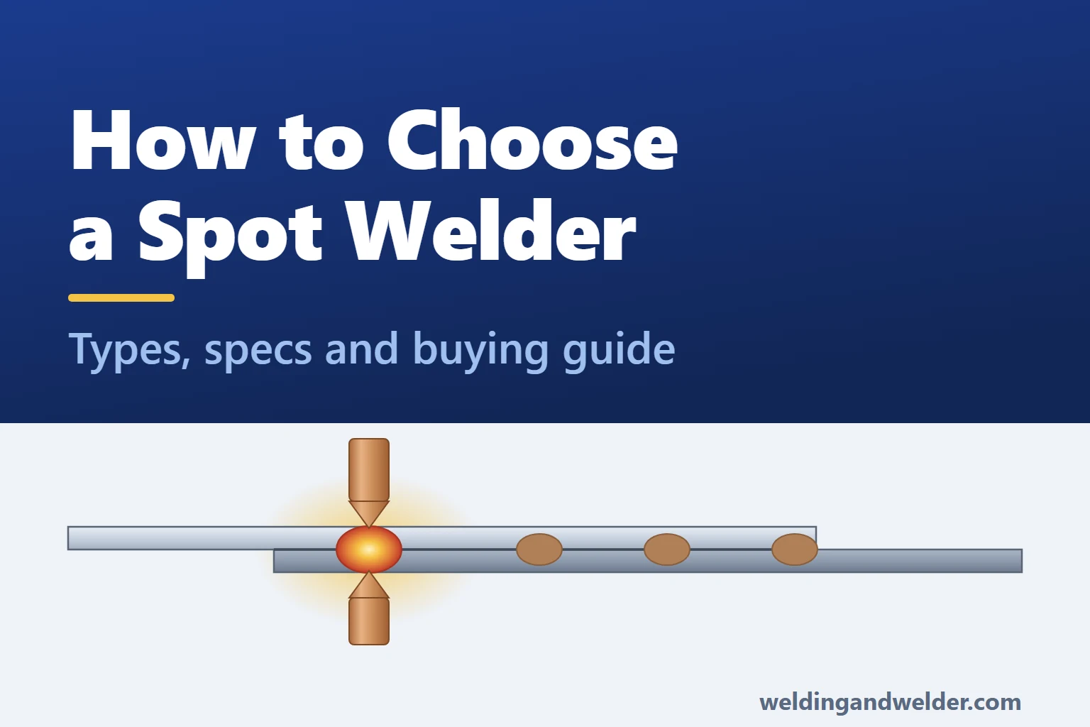
Resistance spot welding joins overlapping metal sheets by squeezing them together while a large electric current heats a small area between them. That area melts and then hardens into a weld, allowing repeatable joints to be made quickly in sheet metal fabrication and vehicle bodywork. Filler metal and shielding gas are not normally needed, and the sheet edges do not need bevelling, although the surfaces still need the preparation specified by the welding procedure.
This guide takes you through how the process works, then looks at the different machine types and the features that matter when choosing one. It also explains how to check the quality of the welds you produce.
In this guide:
How Resistance Spot Welding Works
The process begins with two electrodes, usually made from a copper alloy, clamping the overlapping sheets and passing current through them. In sheet-metal spot welding, that commonly means thousands of amps at only a few volts.
Resistance to the current generates heat within the sheets and at their contact surfaces. With the correct settings and electrode contact, the metal between the sheets becomes hot enough to melt. As the joint heats, its resistance changes, so the point of highest resistance is not necessarily at the sheet interface throughout the weld.
Once the current stops, the electrodes keep pressing while the molten metal cools and hardens. The resulting fused area, called the weld nugget, is what joins the sheets together.
To control this process, you need to consider current, clamping force and weld time together, because changing one affects the result you get from the others:
- More force generally lowers contact resistance, which can reduce heating at the contact surfaces if the current and time stay the same.
- More current usually generates heat faster, although too much can force molten metal out of the joint. Any increase needs to be checked by assessing the result.
When setting up for a job, begin with the machine manufacturer’s settings or the approved welding procedure for the material and sheet combination. Set the required force, then use test pieces to check the current and time. Make any adjustments in a controlled way and confirm the weld quality before moving into production.
On AC controllers, welding time is often set in cycles or half-cycles. At the UK’s 50 Hz mains frequency, one cycle lasts 20 milliseconds, while a half-cycle lasts 10 milliseconds. Medium-frequency DC inverter controllers commonly use milliseconds, so look at the adjustment steps offered by the actual controller when comparing how precisely you can set the time.
Types of Spot Welding Machines
Your first decision is whether you can bring the part to the machine or need to move the welding gun to the part. Bench and floor-standing machines suit parts that are easy to handle, while portable or suspended guns can reach larger assemblies. In either case, conventional two-sided spot welding needs access to both sides of the joint.
| Machine type | What it is | Best suited to |
|---|---|---|
| Portable and suspended guns | A movable gun with either a built-in transformer or a separate power source. Heavier versions can hang from a suitable tool balancer to support their weight. | Vehicle bodywork, site work, large assemblies and anything too big or too fixed to bring to a machine. |
| Bench machines, including rocker-arm designs | A compact machine fitted to a bench, with either a rocker arm that moves the upper electrode in an arc or a mechanism that moves it in a straight line. | Smaller sheet-metal parts, brackets and repair work, within the machine’s rated capacity. |
| Pedestal and column machines | A floor-standing machine with either a rocker arm or straight-line electrode action. The available force, cooling and controls depend on the model. | Repeated production work and larger welding duties, where the machine has the required current, force and access. |
| Multi-spot and special-purpose machines | Equipment built around a particular component, sometimes making several welds in one cycle. | High-volume work on a defined part or product family. |
On a rocker-arm machine, the upper electrode follows a curved path as it closes. Because its angle changes along that path, you need to check tip alignment for the part thickness and arm position you are using.
A linear-action machine moves the electrode in a straight line, making alignment easier to maintain through the stroke. The force available still needs to be checked in the specification, because neither a floor-standing frame nor straight-line action alone tells you how hard the machine can clamp.
AC or Medium-Frequency DC Inverter?
| Feature | Mains-frequency AC | Medium-frequency DC inverter (MFDC) |
|---|---|---|
| Output | Alternating current at mains frequency | The inverter drives a transformer; the output is converted to DC for welding |
| Time control | Often cycles or half-cycles: 20 ms or 10 ms at 50 Hz | Commonly set in milliseconds; check the controller’s resolution |
| Supply loading | Often a single-phase input, including some 400 V machines connected between two supply phases | Many industrial models draw from all three phases to balance the supply load, but check the connection required by the model |
| Coated and high-strength steel | Can weld these materials with suitable capacity, electrodes and settings | Can provide finer current and time control, with suitability determined by the actual machine and welding procedure |
| Cost and complexity | Often lower purchase cost and simpler power electronics | Often higher cost, with more electronic control; compare the actual features |
For many mild-steel jobs and some coated-steel work, a suitable AC machine can provide the capability you need. MFDC is worth considering where finer control or higher output would be useful, but compare current regulation, stored programs and data recording as individual features. The word “inverter” does not guarantee that they are included or establish that the weld quality will be acceptable.
Key Components of Spot Welding Machines
| Component | What it does | What to check |
|---|---|---|
| Transformer | Reduces voltage and allows the high current needed at the electrodes. | The rated power, its stated duty cycle and the usable welding output. |
| Arms and electrode holders | Carry welding current and transfer clamping force to the electrodes. | Available arm lengths and shapes, and their effect on reach, force and current. |
| Electrodes | Press on the sheets and carry current through a controlled contact area, with tips that wear and need maintenance. | Correct material, shape and size for the work, plus replacement and dressing requirements. |
| Control unit | Controls the welding sequence and current setting. More advanced units also measure and regulate current. | Timing steps, stored programs, current feedback, fault limits and any data-recording functions. |
| Force system | Applies the clamping force using a lever, pedal mechanism, air cylinder or another actuator. | The force available with the selected arms and whether it can be set and checked reliably. |
| Cooling circuit | Removes heat from the components included in the machine’s cooling system. | Whether cooling is mandatory, the required flow and temperature, and whether a separate water cooler and flow interlock are needed. |
| Frame | Supports the arms and helps keep the electrode tips aligned under load. | Stiffness and alignment with the arm length and force you need. |
Throat Depth, Arm Reach and Access
Before comparing power ratings, make sure the electrodes can reach the joint and the part fits around the arms and holders.
The arms you choose can affect more than access. On many rocker-arm machines, longer arms reduce the force available at the tips, while arm length and the welding circuit also affect the current available. Ask for both figures with the arms you plan to use, as the headline rating may describe a shorter setup.
When checking a part, measure the distance from the sheet edge to the weld, the flange height and any obstruction. Loading and removal matter as well as whether the tips can reach the joint. Different arms, offset tips or suitable swivel electrodes may solve an access problem, provided their ratings are also checked.
Specifications to Check Before Buying
| Specification | What it means | What to check |
|---|---|---|
| Power rating (kVA) | The transformer’s power rating under stated conditions. | Compare the same type of rating at the same duty cycle, as nominal, maximum and continuous ratings describe different things. |
| Maximum welding current (kA) | The welding current the machine can deliver under stated conditions. | Look for usable welding current rather than short-circuit current, then confirm what is available with your arms, material and workload. |
| Clamping force (daN) | The force pressing the sheets together. One daN is exactly 10 newtons, roughly the weight of a 1 kg mass. | Current and force both need to suit the joint, so confirm the force with the selected arms and operating air pressure, where relevant. |
| Weld time | How long the current flows. | Check how precisely you can adjust it, particularly for thin or coated metal. |
| Duty cycle or welds per minute | The welding workload permitted at a stated current and cooling condition. | Use your actual weld time and current to check the permitted weld rate, because a duty percentage alone does not tell you the welds per minute. |
| Reach and clearance | Electrode reach, arm clearance and the opening available for loading parts. | Check that the part fits and the electrodes can reach every joint. |
| Sheet-thickness capacity | The material and sheet combination the manufacturer rates the machine to weld. | Read the rating for the sheet combination: 2 + 2 mm means two sheets of 2 mm each. Unequal thicknesses or three-sheet joints need separate confirmation of suitability. |
| Power supply | Required voltage, number of supply phases, cable size and circuit protection. | Read the full electrical specification before choosing, as a 400 V rating does not necessarily mean a three-phase machine. |
For a useful comparison, focus on usable welding current, force with your chosen arms, and the workload the machine can sustain. Then ask the supplier to confirm that the machine is rated for your actual material and sheet combination.
Factors to Consider When Buying a Spot Welder
These checks will help you narrow down the options, starting with the work you need the machine to do.
- Material and thickness. List the metals, grades, coatings and sheet combinations you need to join, including the number of sheets and each sheet’s thickness as well as the total.
- Reach and clearance. Measure the distance the electrodes must reach from the sheet edge and the height of any flanges, then check that the part fits between the arms.
- Number of welds. Estimate both the weld rate and the length of each production run so you can confirm that the machine and cooling system will sustain the workload.
- Power supply. Before buying, confirm the electricity supply available where the machine will be used, including the fuse or circuit breaker rating.
- Weld quality and records. Look for suitable current control, repeatable force and saved programs, and establish exactly what the machine measures and stores if records are required. These features help support testing, but do not replace it.
- Weight and handling. Where the operator holds the welding gun, its weight becomes part of the decision. A tool balancer can support the gun and reduce the effort needed to handle it.
- Replacement parts and support. Before choosing a machine, make sure electrode tips, replacement arms and service support are readily available.
You can compare the options in our full range of spot welders, including Tecna models.
Common Features of Spot Welders
- Saved weld settings. Stored programs let operators recall settings for different jobs, provided the electrodes, material and setup are confirmed as correct before the program is used.
- Separate timing controls. These let you set how long the sheets are clamped before current starts, how long welding lasts, how long the electrodes hold the nugget as it hardens, and the pause before another cycle. The stages are often called squeeze, weld, hold and off times.
- Gradual or pulsed current. Some controllers can raise the current gradually or apply it in several pulses. Use these functions where the welding procedure calls for them, as they are not automatically suitable for every coated or thick sheet.
- Current regulation. As electrical conditions change, the controller adjusts the power to help maintain the set current within the machine’s operating limits.
- Water cooling and flow monitoring. Cooling removes heat, while a flow switch can prevent welding if the water flow is inadequate, provided it is fitted and connected to stop the cycle.
- Interchangeable arms and tips. These help adapt the machine to different joints, but each change calls for another check of access, alignment and available current and force.
- Guards and suitable controls. The safety arrangements need to suit both the machine and the work, with properly designed two-hand controls available as one option on suitable machines.
- Weld counters and data recording. Counters help you plan electrode maintenance, while data recording may cover selected settings, measured current and fault indications, depending on the model.
Welding Different Materials
| Material | How it behaves | What to watch for |
|---|---|---|
| Uncoated mild steel | Usually the easiest material to spot weld, with a wider range of settings that produce good results. | Start with the actual grade, thickness, electrode size and machine when choosing settings. A generic mild-steel setting is only a starting point. |
| Galvanised and zinc-coated steel | The zinc coating melts before the steel and changes how the current passes through the joint. | Usually needs more current and force than uncoated steel, together with a suitable time or pulse sequence. Zinc can alloy with the tips and shorten electrode life, and the fume must be assessed and controlled. |
| High-strength and ultra-high-strength steel | May need higher clamping force and a specific welding sequence; heat and rapid cooling can change the steel’s properties around the weld. | For vehicle repairs, follow the instructions for the component. Some methods specifically require spot welding, so high-strength steel should not automatically be treated as unsuitable. |
| Stainless steel | Many grades resist current more and lose heat more slowly than mild steel, so they heat differently. | Often needs less current than mild steel of the same thickness, but use settings for the particular grade and check indentation, distortion and weld performance. |
| Aluminium | Conducts heat and electricity readily, while its oxide layer affects electrical contact. It generally needs high current and a short, carefully controlled weld. | Confirm the machine’s stated aluminium capacity along with its force and electrode requirements, then follow the procedure for surface condition and tip maintenance. |
Coatings need attention when planning both the weld settings and the fume controls. Assess the work and provide suitable ventilation or extraction: general ventilation may be enough for low-intensity spot welding on clean, uncoated metal, but that should not be assumed for coated material or heavier production.
For help comparing equipment, our guide to choosing and maintaining welding fume extractors explains the options, while the welding ventilation guide covers ventilation and extraction requirements.
Checking Spot Weld Quality
A spot weld’s appearance cannot establish its strength, so checking the setup commonly involves welding test pieces made from the same material, coating and sheet combination, then breaking them apart. This is destructive testing, and both the test method and the acceptance criteria need to be those required for the job.
Weld size. Start with the diameter required for the material, sheet combination and specification. For some steel-sheet joints, a common target is 5 times the square root of the sheet thickness in millimetres, giving 5 mm for 1 mm sheet. This is not a universal minimum, so follow the specified target, minimum and measurement method. The button left by a peel test is not always the same size as the fused nugget.
Weld spacing and distance from edges. When welds are close together, some current can pass through an earlier weld, reducing the current available to form the new one. This is known as shunting. Placing a weld too close to an edge can also allow molten metal to escape or leave too little material to carry the load, so use the spacing and edge distances specified for the joint.
Electrode marks. Some indentation is normal, with the permitted depth depending on the job. If the marks are deep, check the applicable limit and investigate whether excess heat, force, poor tip shape or alignment is the cause. Appearance alone cannot tell you how strong the weld is.
Electrodes, Spares and Cooling
As electrode tips wear and spread, the current has a larger contact area to pass through. This can reduce heating in the joint and produce smaller nuggets even when the machine settings have not changed. Surface contamination and poor alignment can also affect the result.
| Item | What it does |
|---|---|
| Electrodes and caps | The tip shape affects both contact area and access, so replacements need to match the holder and welding procedure in material, shape and dimensions. |
| Arms and accessories | Different lengths and shapes let the same machine reach a wider range of joints. |
| Spares | Includes holders, adaptors, flexible current-carrying shunts and cables. Keeping connections sound matters because loose or damaged ones add resistance, generate heat and can limit welding current. |
| Water coolers | Remove heat from water-cooled components, with the flow, temperature and coolant quality matched to the machine manufacturer’s requirements. |
Dressing restores the tips to their specified shape and should be done before wear starts to cause poor welds. Base the interval on the material, weld count and wear you observe, replacing tips once they reach their wear limit. After dressing or replacement, retest as the procedure requires.
Power Supply and Installation
Spot welders use power in short, high bursts, so the installation needs to cope with both the peak demand and the overall workload. Average energy use alone does not describe what the supply must handle.
- 230 V single phase: Some smaller machines use this supply, although they may still need a dedicated circuit. Check the input current and required fuse or breaker.
- 400 V supplies: The voltage alone does not tell you how the machine connects. Some AC welders use a single-phase connection between two phases, while many industrial MFDC models use all three. Follow the nameplate and installation instructions for the particular machine.
- Compressed air: Pneumatic machines need the specified pressure, flow and air quality throughout repeated cycles, so make sure the supply can maintain all three.
- Cooling water: Follow the specified flow, pressure and temperature requirements. Where the machine requires water cooling, it must be connected and running even for a short job.
- Space and positioning: Plan enough room to load and support parts, move the gun or arms and change tips, while allowing safe working around the closing electrodes.
Arrange for a competent electrician to confirm the supply and installation requirements before the machine arrives.
Using a Tool Balancer with a Spot Welder
A tool balancer can take much of the weight of a welding gun and its supported cables and hoses, reducing the effort of handling it and helping the operator position it steadily. Choose and install the balancer around the actual load it will carry and the movement needed for the work.
- Choose the right weight range. Add the gun’s weight to that of every cable or hose section the balancer will support, then keep the total within its rated range and adjust it as instructed.
- Check the travel. Make sure the tool can reach every working position without pulling the rope beyond its permitted travel.
- Mount it as the manufacturer specifies. The support needs to be suitable and let the balancer align with the load, avoiding rope rubbing, snagging or excessive sideways pull.
- Inspect the suspension and safety devices. Include the rope, hooks, fixings and specified secondary safety attachment in the checks, following the inspection and replacement instructions.
Maintenance and Safety
| Interval | Checks |
|---|---|
| Before use | Check tip condition and alignment, cooling flow, air supply, guards and controls. Look for damaged cables or shunts and signs of overheating. |
| At the interval set for the work and equipment | Dress or replace tips according to wear and weld count. Check arm and holder connections and look for air or water leaks. Follow the safe maintenance instructions. |
| At planned service and verification intervals | Have competent people verify force, current and electrical connections as required. Retest weld quality after relevant changes and at the frequency specified for production. |
Safety
- Trapped fingers or hands. The force needed to close the electrodes also creates a trapping hazard. Keep hands clear of the closing area and use the guarding, controls and operating method specified for the machine.
- Flying molten metal. Even though normal resistance spot welding does not use an open arc, metal can be ejected from the joint. Wear suitable eye protection and screen people nearby.
- Welding fume. The material, coatings and amount of welding determine the controls needed. Low-intensity work on clean, uncoated metal may need only good general ventilation, while other work may call for extraction or additional controls. You can explore the options in our fume extraction equipment range.
- Hot surfaces. The welded parts, electrodes and arms can remain hot after welding.
- Electrical and stored-energy hazards. Low welding voltage does not remove the danger from mains-voltage parts. Competent people must carry out maintenance using the required isolation procedure for electrical, air-pressure and other stored-energy sources.
- Protective equipment. Wear suitable eye protection, gloves and protective clothing. See our safety equipment range.
In Great Britain, PUWER covers the safe use of work equipment, while COSHH covers hazardous substances such as welding fume. Employers must assess the risks and put suitable controls, training and maintenance in place. For Northern Ireland, corresponding regulations and HSENI guidance apply.
Spot Welding in Vehicle Repair
The vehicle manufacturer’s repair method determines how replacement panels must be joined. Changing a factory spot weld to another joint type can alter its performance, so use a plug weld, brazed joint or other alternative only where that method permits it.
- Follow the manufacturer’s repair instructions. Use these to establish the welding method, where to place the welds and which parts must be replaced rather than repaired.
- Check the exact component and steel grade. High-strength or boron steel is not automatically ruled out for spot welding; some replacement procedures require it, even where heat straightening or sectioning may be prohibited. Let the instructions for that vehicle and part guide the work.
- Check the required equipment. The machine, arms and electrodes need to meet the repair method’s requirements for current, force, access and control. Use approved equipment where the manufacturer specifies it.
- Understand BS 10125. This British standard sets requirements for vehicle damage repair processes, equipment and staff competence, alongside the vehicle manufacturer’s repair instructions, which must still be followed.
- Test before welding the vehicle. Make test samples that match the material, coating and sheet combination, then carry out the manufacturer’s specified destructive test and assess the results against its acceptance criteria. Automatic machine settings alone are not enough to establish weld quality.
If you handle vehicle repairs as well as fabrication, a suitable MIG welder may be useful alongside a spot welder, with the process and consumables chosen to meet each repair method.
Frequently Asked Questions
What thickness can a spot welder join?
Start with the rating for the actual material and sheet combination you plan to weld. For example, 2 + 2 mm means two sheets that are each 2 mm thick; it does not establish that every other 4 mm stack will be suitable. Unequal thicknesses, coatings and three-sheet joints can affect the machine’s capability, as can the arm length and production rate.
What does daN mean on a spot welder specification?
daN stands for decanewton, a unit used to express force. One daN is exactly 10 newtons, roughly the weight of a 1 kg mass, so a 200 daN rating means 2,000 newtons of clamping force. When comparing ratings, look at the arm length and, for pneumatic machines, the air pressure used to achieve that figure.
Can I spot weld galvanised steel?
Yes, provided the equipment and settings suit the job. Zinc-coated steel generally needs more current and electrode force than uncoated steel, and the coating also affects tip wear. Follow the dressing schedule and test the welds, while assessing the fume and providing the controls needed for the actual work.
Can I spot weld aluminium with a standard spot welder?
The manufacturer needs to rate the machine for the aluminium grade and sheet thicknesses you want to join. Aluminium generally requires much higher current than steel, along with suitable electrodes, controlled force and short weld times. Some capable AC machines can do this work, so MFDC is not the only possible power source. A steel thickness rating, however, cannot be assumed to apply to aluminium.
Do I need water cooling?
The machine instructions determine this. A water-cooled model needs its specified cooling even for a short job, while an air-cooled model must stay within its rated duty. For production, check that the flow, temperature and cooling capacity meet the requirements at your welding current and weld rate.
What is the difference between an AC and an inverter spot welder?
An AC machine delivers alternating welding current at mains frequency, whereas an MFDC machine uses an inverter and rectifier to supply direct welding current, often with finer timing control. Some AC controllers also offer half-cycle timing, and the supply arrangements vary between machines. When choosing, compare current control, usable output, supply requirements and data recording on the actual models.
How do I know if a spot weld is any good?
Use the required test method on samples that match the material, coating and sheet combination you will weld. A peel test may pull a button from one sheet, which can then be measured against the required size. A break between the sheets can also happen in a fused but brittle weld, so it does not establish that current or time was too low. Judge the result against the specified acceptance criteria and investigate any failures.
Are cordless battery spot welders any use?
They can be useful for the thin tabs or light materials they are designed to weld. They are not substitutes for equipment specified for structural sheet-metal or vehicle repairs, so compare the rated material, sheet combination, force and weld quality with the work you need to do. The power source alone does not tell you whether a tool is suitable.
You can browse our spot welding machines or use the technical enquiry form for help comparing suitable machines. Send us the material, coating, individual sheet thicknesses, required weld rate and access dimensions so we can help you assess the options.