Manual Metal Arc (MMA) welding, also known as Shielded Metal Arc Welding (SMAW) or stick welding, is widely used for fabrication, construction and repairs. The flux-coated electrode provides both filler metal and protection for the weld pool, which makes it useful on site without a separate shielding-gas supply. Clean material, a suitable electrode and a controlled arc are still essential to getting good results.
This guide takes you through the common MMA welding problems, how to recognise them and what to check before adjusting the settings. Cleaning the weld may reveal some imperfections, while others remain hidden inside it. Use the job specification to decide what is acceptable, as a neat surface alone cannot establish that the joint is sound.
In this guide:
Quick Reference: MMA Welding Problems and First Checks
Use the table to narrow down the possible causes, then turn to the relevant section for a fuller explanation. Where a welding procedure specification (WPS) applies, keep adjustments within its limits. Changes to joint preparation, consumables or the repair method must follow that procedure rather than being worked out informally at the bench.
| Problem | What it looks like or means | Common causes | First checks |
|---|---|---|---|
| Spatter | Metal droplets scattered around the weld. | An unstable or long arc, unsuitable current or polarity, damaged electrodes, arc blow. | Check the electrode settings and condition, then shorten and steady the arc. |
| Arc blow | The arc bends away from the intended weld line. | An uneven magnetic field, the return-current path or residual magnetism. | Check the return connection and trial changes to its position or the travel direction. AC may help where permitted. |
| Porosity | Gas cavities on the surface or inside the weld. | Moisture, contamination, damaged shielding or unsuitable technique. | Clean and dry the joint, check electrode storage and keep the correct arc length. |
| Slag inclusion | Slag trapped within the weld or between runs. | Incomplete cleaning, pockets between beads, unsuitable angle or settings. | Remove slag between passes and check access, bead placement and the arc position. |
| Undercut | An unfilled groove beside the weld. | Excessive current, a long arc, fast travel or poor control at the bead edges. | Check current and arc length, then adjust travel and edge dwell. |
| Overlap | Weld metal spreads onto the surface without fusing to it. | A large pool running ahead of the arc, low heat at the joint face or unsuitable angle. | Keep the arc at the leading part of the pool and review travel speed and current. |
| Lack of fusion | The weld fails to fuse to a joint face or earlier run. | Poor access or cleaning, unsuitable settings, or the arc missing the joint face. | Check preparation and technique as well as current; adding more metal will not repair the unfused area. |
| Incomplete penetration | The weld does not reach the depth required by the design. | Incorrect root gap or face, poor access, unsuitable electrode size or settings. | Compare the fit-up and root technique with the drawing and procedure. |
| Burn-through | A hole forms when the molten pool breaks through. | Excessive heat for the joint, slow travel, a wide gap or poor pool support. | Check fit-up, electrode size, current and travel; use backing only where the procedure permits it. |
| Cracking | A fracture in the weld or surrounding material. | Hydrogen, susceptible material, contraction stresses, bead shape or restraint. | Stop and identify the crack type and cause before planning removal and repair. |
| Electrode sticking | The electrode attaches to the work during starting or welding. | An arc held too short, low current, poor connections or electrode/machine incompatibility. | Check the circuit and recommended settings, then practise a controlled strike and lift. |
| Distortion | The assembly bends, twists or moves out of alignment. | Uneven heating and shrinkage, excessive weld size or an unbalanced sequence. | Check the specified weld size, fit-up, tacking and welding sequence. |
Current, Arc Length, Angle and Travel Speed
With a suitable electrode, joint preparation and machine in place, the result depends strongly on four connected variables: current, arc length, electrode angle and travel speed. Where practical, adjust one at a time on a representative test piece so you can see whether the change improves the weld.
Current
Begin with the manufacturer’s current range for the exact electrode type and diameter, together with any settings required by the WPS. Diameter alone does not determine current, and a setting that works flat can produce too large a pool when welding vertically or overhead. Follow the product’s guidance for the position instead of applying the same percentage reduction to every rod.
Listen to the arc and look at the bead for clues, but avoid treating either as a diagnosis on its own. A long arc, poor connection or incorrect polarity can look like a current problem, so investigate those before changing the amperage.
| What you notice | Current may be too low | Current may be too high |
|---|---|---|
| Arc behaviour | Repeated sticking or difficulty maintaining the arc. | A forceful, erratic arc with excessive spatter. |
| Pool and bead | A sluggish pool and a narrow, raised bead with poor fusion at the edges. | A pool that is difficult to control, with undercut or burn-through. |
| What to check next | Confirm the recommended range, polarity and sound electrical connections. | Confirm the recommended range, arc length, travel speed and suitability for the material thickness. |
Arc Length
Arc length is the gap between the electrode’s metal tip and the work. A useful starting guide is to keep it no longer than the electrode’s core diameter, with the actual gap chosen for the product and technique. Basic low-hydrogen electrodes usually need a particularly short, controlled arc, while still keeping the metal tip out of the pool.
Keeping that gap consistent matters: an unnecessarily long arc can become unstable and weaken the protection around the molten metal, increasing spatter and porosity. Too small a gap can extinguish the arc and leave the electrode stuck to the work. As the electrode burns away, feed it towards the work to maintain the gap through the run.
Electrode Angle
Electrode position involves two angles. The travel angle describes its lean along the weld, while the work angle describes its position across the joint. For many flat and horizontal MMA welds, start with a drag angle of about 5 to 15 degrees, keeping the holder slightly ahead of the arc in the direction of travel.
The angle changes with the position and joint, so dragging is not a universal technique. Vertical-up welding commonly uses a near-perpendicular or slight push angle, according to the electrode and procedure. For an equal-leg fillet joining similar thicknesses, about 45 degrees is a starting work angle; unequal leg sizes or different thicknesses may need a different aim.
Travel Speed
Travel speed determines how much heat and filler metal go into each length of joint. Move too quickly and the weld can be undersized or poorly fused; move too slowly and a large pool can run ahead, shielding the joint face from the arc. Keep the arc near the leading part of the pool, aiming for a steady bead width and controlled fusion at both edges.
When weaving, match the width and pauses to the electrode, position and procedure. A wider weave changes heat input and can leave slag pockets or poorly fused edges, so it is not automatically a better way to fill the joint. Our guide to welding positions and technique explains how to adapt the approach when moving away from flat-position work.
Weld Spatter
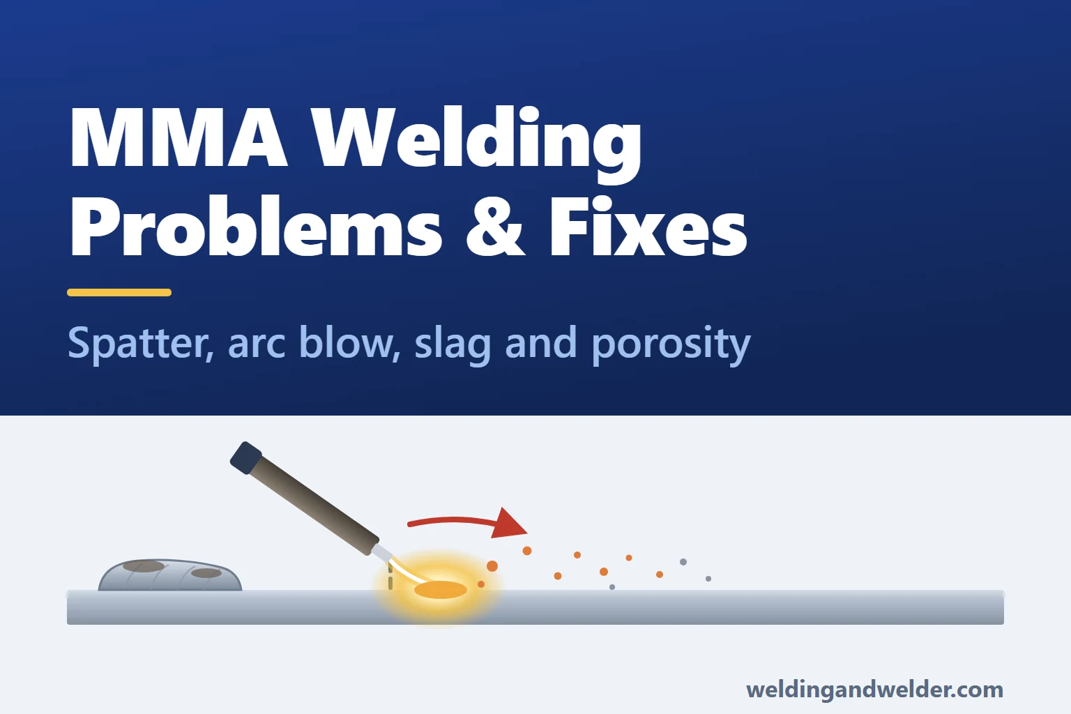
Spatter is made up of droplets thrown from the arc or weld pool that stick to surrounding surfaces. Some electrodes normally produce a degree of spatter, but a sudden increase often suggests a change in arc length, settings, electrode condition or magnetic arc blow. Besides adding cleaning work, the deposits can obscure the weld surface during inspection.
Start by comparing current and polarity with the electrode data sheet, then assess how steadily you are holding the arc. A family description such as “rutile” or “low hydrogen” is not enough to choose the connections, because polarity requirements vary within those groups. The product specifies whether it can use DCEP, meaning electrode positive, DCEN, meaning electrode negative, or AC.
After addressing the cause, a suitable anti-spatter product can make the deposits easier to remove. Follow its application instructions without contaminating the joint faces, bearing in mind that it cannot fix the underlying welding problem. For stainless steel, use suitable cleaning tools and restore the specified finish wherever heat damage or contamination could reduce corrosion resistance.
Arc Blow: Why the Arc Wanders
Magnetic arc blow is the bending of the arc away from the intended weld line by an uneven magnetic field. It mainly affects DC welding and may appear near plate ends, changes in joint geometry or magnetised material. Even with a steady hand, the arc can wander, leaving spatter, an uneven bead and poor fusion.
Why It Happens
Welding current creates a magnetic field along its path through the electrode and workpiece. The return connection and surrounding steel influence that field, and residual magnetism from earlier handling or magnetic inspection can add to it. As a result, moving the clamp or reversing travel may help on one joint but make the problem worse on another.
The work-return clamp is often called the earth clamp, but its purpose is to carry welding current back to the machine, not to replace the equipment’s protective earthing. It needs good contact, although cleaning a loose connection will not, by itself, remove magnetism from the steel.
How to Reduce It
Establish a short, stable arc and a sound return connection before trying a different clamp position or travel direction. There is no rule that always requires welding towards or away from the clamp. A smaller electrode at a suitable lower current may help too, as long as the joint still receives the fusion and heat input it requires.
Where the machine, electrode and procedure permit it, AC can reduce magnetic arc blow. If the problem persists, the residual field may need to be measured and the component demagnetised. Additional return leads, compensating cable coils or joint changes need planning by someone competent to assess them; they should not be improvised during welding.
Include cables and connections in the investigation, replacing any that are damaged or unsuitable. Our work-return clamps and electrode holders ranges cover the components at the two ends of that circuit.
Porosity
Porosity develops when gas becomes trapped in the solidifying weld, leaving rounded pores or longer cavities. Some reach the surface and others stay hidden, with their significance depending on size, number and position. Judge them against the acceptance criteria rather than assuming that a few pores are harmless.
Begin with the condition of the joint and electrode. Moisture in the coating, oil, paint, rust and other contamination can introduce gas into the pool, so remove it using suitable preparation methods, including grinding discs where appropriate. Make sure the prepared surfaces are dry before welding, and provide suitable dust and fume controls for both coating removal and welding.
Then look at arc length and the conditions around the pool. MMA is generally less wind-sensitive than processes with an external shielding-gas supply, but strong draughts can still disrupt its protection, as can a long or wandering arc. Correct these conditions and review electrode storage before assuming the answer is more current.
Slag Inclusions
The flux coating forms a slag layer that protects the cooling weld. If some of it becomes trapped in the metal, often between passes or in a pocket beside an earlier bead, it forms an inclusion. This is particularly associated with flux-based processes such as MMA, although inclusions are not limited to them.
Clean the slag from every run and from any tack that will become part of the finished joint. An accessible, well-shaped bead may need only chipping and brushing, while narrow grooves or deep pockets may require grinding. Use suitable eye protection and inspect the cleaned surface before adding the next pass.
Slag recurring in the same place is a reason to examine bead placement and access. A high, convex bead or unfilled undercut can create a pocket that the next pass bridges over, while an unsuitable angle or travel speed may let slag move ahead of the arc. Adjust within the procedure and maintain enough heat for fusion, without relying on another run to melt away buried slag.
Undercut and Overlap
Undercut and overlap both occur at the weld edge, or toe, but cleaning the weld reveals the difference in shape. Undercut is a groove in the parent metal; overlap is a lip of weld metal spread onto the surface without fusing to it.
Undercut
Undercut forms where the arc melts the parent metal beside the weld and the pool fails to refill the groove. It can reduce the effective section and concentrate stress, particularly under repeated loading. Compare the groove’s size and extent with the specified limits to decide whether it is acceptable.
Several factors can contribute, including excessive current, a long arc, fast travel and an unsuitable electrode angle. Consider them together before changing the setting or technique responsible for the groove. Where weaving is permitted, a brief, controlled pause at each edge can help fill the toes, but too much width or dwell can introduce other problems.
Overlap
The extra metal in an overlap may resemble reinforcement, but the lip has not fused to the surface beneath it. A large pool running ahead of the arc or too little heat reaching the joint face can produce this result. Making the bead larger leaves that unfused boundary in place.
Keep the arc near the leading part of the pool and direct it at the area that needs to fuse. If metal is piling up, steadier or faster travel may help; if the current is genuinely too low, an increase within the approved range may be needed. Include the angle and electrode size in the check, as different causes can produce the same appearance.
Lack of Fusion
Lack of fusion means the weld has not fused to a joint face or an earlier run. It can lie at a side wall, between passes or at the root, hidden beneath a smooth surface bead. The sharp unfused boundary can be significant when the joint is loaded.
First establish whether the arc can reach clean surfaces where fusion is required. A narrow preparation, oversized electrode, trapped slag or unsuitable work angle can prevent fusion even with a reasonable machine setting. Low current or excessive travel speed can also contribute, while travelling very slowly may let the pool run ahead and shield the face from the arc.
Use the applicable procedure to correct the preparation or technique, then remove unacceptable unfused material before repairing the weld. Finding internal lack of fusion may require ultrasonic or radiographic examination, with the method chosen for the joint and the imperfection’s orientation, as the inspection section explains.
Lack of Penetration and Burn-Through
Lack of Penetration
Incomplete penetration means the weld has not reached the depth required by the design. In a joint intended for full penetration, an unfused root can leave less material to carry the load than the design allows for. Before judging the result, check the drawing: a joint deliberately designed for partial penetration is acceptable when made to its specified detail.
Start by comparing the root gap, root face and preparation angle with the drawing. The root face is the un-bevelled land at the bottom of the preparation; if it is too thick, or the gap too tight, the arc may struggle to reach the root. Electrode size, angle and travel speed also affect access and fusion, so consider those before changing the current.
A smaller electrode for the root run or an adjustment to the settings may help, but changes to the gap, bevel, backing or welding from the second side must follow the procedure. Where back-gouging is specified, remove material until you reach sound metal, then check the prepared root before welding from the second side.
Burn-Through
Burn-through occurs when the molten pool breaks through the joint, leaving a hole. Thin material and open roots are particularly susceptible because the heat, gap and pool size can be difficult to balance. Begin with the fit-up, then review electrode size, current and travel speed to bring the pool under control.
Backing or a planned sequence of shorter runs can help in suitable applications, provided the design and procedure allow them. A required continuous weld must not be replaced with intermittent welds simply to reduce heat. Whatever approach you use, the finished joint still needs the specified size, continuity and penetration.
Cracking
If you find a crack, stop and establish its cause before attempting a repair, as it can grow under load. Welding over it will not reliably remove it, and repeating the same method may produce another crack. The mechanisms below call for different controls, so a change that helps with one type may do little for another.
Hydrogen Cracking (Cold Cracking)
Hydrogen cracking occurs when hydrogen, a susceptible microstructure and tensile stress combine as the joint cools. It may develop in the weld metal or in the heat-affected zone, the surrounding parent metal changed by the welding heat. Moisture in electrode coatings and contamination on the joint are important sources of hydrogen, while the material’s composition, cooling rate and restraint influence how likely it is to crack.
To control that risk, use the specified low-hydrogen consumables, store them correctly and clean the joint faces, then follow the required preheat and interpass temperatures. Interpass temperature is the joint’s temperature before the next run, and both its minimum and maximum limits can matter. Use the limits established for the material and procedure, as adding more heat or slowing the cooling is not automatically better for every steel.
Hydrogen cracks can take time to appear, so an inspection immediately after welding may not be the final check. Follow the waiting time in the applicable specification rather than assuming every joint needs the same 48-hour delay. There is also no single temperature threshold above which all risk of hydrogen cracking disappears.
Solidification Cracking (Hot Cracking)
Solidification cracking develops as the weld metal changes from liquid to solid and cannot withstand the stresses caused by contraction. The cracks often follow the bead’s centreline, with the risk affected by composition, contamination, restraint and bead shape. In steels, sulphur and phosphorus can play an important part, particularly in some free-cutting grades.
Look at the bead shape as part of the investigation: both a deep, narrow bead and a wide, thin bead bridging an excessive gap can be vulnerable. Check the material and fit-up, then choose a suitable consumable and bead profile instead of assuming that lowering the current will solve the problem. You may also need to control travel speed and dilution, which is the amount of parent metal mixed into the weld.
Crater Cracking
The depression left when the arc stops is called a crater. If that final pool is too thin or poorly filled, it can crack as it solidifies, sometimes leaving a star-shaped pattern. Use the electrode’s recommended finishing technique to fill the crater, then check it before restarting or adding another pass. Any crack needs to be assessed and removed as part of the repair.
Lamellar Tearing
Lamellar tearing occurs in the parent plate, usually as stepped cracks running roughly parallel to its surface. It develops when welding shrinkage pulls through the thickness of rolled plate that has poor ductility in that direction, often around highly restrained T-joints or fillet welds. Prevention may therefore involve the material and joint design as well as the welding method, with a revised joint detail, suitable plate properties or an engineered buttering procedure among the possible measures.
Distortion
As an assembly heats and cools, its different parts expand and contract by different amounts. This can leave the work bent or twisted, or change the joint gap as welding progresses. Oversized welds and an unbalanced sequence can make the distortion worse by introducing more shrinkage than the design needs.
Plan the fit-up, tacks and welding sequence before starting, and keep to the specified weld size. Balanced runs, suitable fixtures or an established back-step sequence can help, although restraint also increases stress and may raise the risk of cracking. Any pre-setting or straightening method needs to suit the material and fabrication requirements; forcing the part back into shape will not correct an unsound weld.
Electrode Sticking and Arc Starting Problems
A sticking electrode is a process problem rather than a weld imperfection, but the interruptions can leave poor starts. Check the current, arc length and electrical circuit together, and make sure the machine supports the electrode you are using. This matters particularly with some cellulosic electrodes, including E6010, whose demands on the power source are beyond the capability of some inverters.
| Problem | Possible causes | What to check |
|---|---|---|
| Electrode sticks when starting | Low current, poor contact or remaining on the surface after striking. | Use the recommended current and a controlled scratch or tap start, lifting promptly to establish the arc. |
| Electrode sticks during the run | The gap closes as the rod is fed, the current is too low, or the circuit is unreliable. | Maintain a steady, short arc and check current and connections rather than deliberately using a long arc. |
| No arc forms | The return circuit is incomplete, connections are poor, or the machine is not set correctly. | Check the machine setup and clean return contact; isolate the supply before inspecting or repairing connections. |
| Arc starts, then repeatedly goes out | Unsuitable current or polarity, electrode condition, or power-source incompatibility. | Check the electrode data sheet and machine manual, including any relevant arc-force setting. |
| A partly used electrode is difficult to restart | An insulating slag cap covers the metal tip. | Follow the electrode maker’s restriking method, avoiding damage to the surrounding coating. |
| Arc wanders despite a steady hand | Magnetic arc blow or a damaged electrode. | Check the electrode and return arrangement, then follow the arc-blow guidance above. |
If the machine has hot start, it can temporarily increase current to help establish the arc, while arc force changes the response as the arc becomes short. These controls can help with a suitable electrode, but poor connections and damaged cables still need attention. Follow the machine instructions when adjusting them, especially on thin material, rather than simply turning them up.
Keep arc strikes within the intended weld area or on an approved run-on tab, as stray strikes can damage the parent metal and may need inspection. If a rod sticks, release it using the machine’s safe procedure instead of repeatedly overheating it against the work. Replacement leads, holders and related parts are available in our MMA welding accessories range.
Electrode Storage, Moisture and Redrying
If the result changes while the settings and technique stay the same, look at the electrodes’ condition. Moisture absorbed by a basic low-hydrogen coating can increase hydrogen in the weld and contribute to porosity or cracking, which makes storage part of quality control. The treatment needs to suit the coating: keeping every type of rod in the same hot oven is not a suitable general approach.
Leave packaging intact until the electrodes are needed and follow the manufacturer’s storage conditions. Some sealed packs allow direct use for a stated period after opening, while other products or procedures require heated holding. Once a pack is open, keep track of the permitted exposure time rather than leaving it on the bench indefinitely.
Holding and redrying serve different purposes. A holding oven or heated quiver keeps correctly conditioned electrodes ready for use, whereas redrying uses a specified temperature and time to restore electrodes where the manufacturer permits it. Follow the exact product instructions, including any limit on repeated cycles, and check the equipment’s capability: a quiver may not reach redrying temperatures. A domestic oven is not an appropriate substitute for controlled electrode-conditioning equipment.
Before applying heat, check which coating you are dealing with. Rutile electrodes must not automatically receive the high-temperature treatment used for some basic types, while cellulosic electrodes contain moisture as part of their coating system and can be damaged by that treatment. Follow their specific handling instructions, discard rods with badly damaged or contaminated coatings, and do not assume baking will make an electrode of unknown condition fit for use.
Browse electrode ovens and quivers or read the guide to electrode storage and conditioning equipment for more detail on the equipment.
Choosing the Right Electrode
Before choosing a diameter, match the electrode to the parent material, required weld properties, welding position and power source. The coating family gives you an idea of how it handles, while the full classification and product data establish whether it suits the job. Use the examples below as common starting points, with the job’s consumable specification taking precedence.
| Type | Example classifications | Practical characteristics | Common applications |
|---|---|---|---|
| Rutile | E6013; some E6012 types. | Often easy to start, with a smooth arc and manageable slag. Check polarity and positions; these are not low-hydrogen electrodes. | General mild-steel fabrication and suitable maintenance work. |
| Basic / low hydrogen | E7018, E7016. | Used where hydrogen control and specified mechanical properties matter. Need appropriate storage and a controlled arc. | Structural work and other joints with specified strength, toughness or hydrogen requirements. |
| Cellulosic | E6010, E6011. | A forceful arc and fast-freezing deposit, with specific machine and polarity requirements. They are not low-hydrogen types. | Pipe roots and positional work under a suitable procedure, including specified vertical-down applications. |
| Stainless steel | For example, E308L-16, E309L-16 and E316L-16. | Select the deposit for the materials and service conditions; the full suffix also affects usability. | Stainless fabrication and specified dissimilar joints. 309L is often used for stainless-to-carbon-steel joints, but is not universal. |
| Cast iron | ENi-CI, ENiFe-CI. | Nickel or nickel-iron deposits chosen to suit the casting, repair procedure and machining needs. | Suitable cast-iron repairs, with heat control and preparation tailored to the casting. |
| Hardfacing | Product-specific alloy and classification. | Choose for the wear mechanism, impact, temperature and layer requirements, not hardness alone. | Wear-resistant surfaces on plant and tooling; a separate build-up alloy may be needed underneath. |
Some hardfacing deposits are intended to develop a controlled pattern of check cracks. This is a feature of particular overlay products, so it should not be used as a basis for accepting cracks in joining welds. To explore the consumable options, browse our MMA stick electrodes or read the guide to choosing the right electrode.
Inspecting Welds and Deciding What Is Acceptable
When assessing a weld, it helps to distinguish between an imperfection, a departure from the ideal weld, and a defect, an imperfection that exceeds the applicable acceptance criteria. Those criteria come from the drawing, contract or application standard. A good appearance or general rule of thumb cannot, on its own, establish whether the weld is acceptable.
BS EN ISO 6520-1 provides the terminology and reference numbers for geometric imperfections in fusion welds. Where the job calls for it, BS EN ISO 5817 specifies quality levels B, C and D for certain fusion-welded joints in steel, nickel, titanium and their alloys, with B the most stringent. Check which requirements apply to the work, as other application codes may set different acceptance and inspection requirements.
Begin by visually examining the cleaned weld, comparing its size, profile, starts, stops and visible imperfections with the specification. Any further non-destructive testing (NDT) needs to suit the material, joint geometry and type of problem being sought. The methods below each have strengths and limitations, so choose on that basis rather than treating them as a simple ranking by cost or quality.
| Method | What it can reveal | Important limits |
|---|---|---|
| Visual testing (VT) | Visible undercut, overlap, surface pores, some cracks, incorrect size or profile. | Needs clean surfaces and suitable access; it cannot establish internal soundness. |
| Penetrant testing (PT) | Imperfections open to the surface, such as fine cracks and pores. | Used on suitable non-porous materials with a clean surface and a compatible test system; it does not find sealed internal flaws. |
| Magnetic particle testing (MT) | Surface and some near-surface imperfections. | Only suitable for ferromagnetic materials. Residual magnetism may need attention before further welding. |
| Ultrasonic testing (UT) | Internal imperfections, including many cracks and unfused interfaces. | Performance depends on orientation, material, thickness, access and the chosen technique. |
| Radiographic testing (RT) | Internal porosity, slag and other changes in thickness or density. | Tight planar imperfections can be difficult to detect when their orientation is unfavourable to the beam. |
If inspection reveals an unacceptable imperfection, establish how far it extends and what caused it before removing material. Follow the specified repair method, checking the excavation as required before re-welding and re-inspecting. A cosmetic pass must not be used to cover a crack or unfused region, and where delayed cracking is a concern, allow the required time before final inspection.
When arc blow appears after magnetic particle testing, residual magnetism is worth investigating, although it is not the only possible explanation. Check the magnetic field and return arrangement so the next repair does not repeat the problem.
MMA Welding Problems FAQ
What is arc blow in welding?
Magnetic arc blow occurs when an uneven magnetic field deflects the welding arc. It mainly affects DC welding, with the return-current path, joint geometry and residual magnetism in the steel all influencing it. Even when you hold the electrode steadily, the deflected arc can leave an unstable bead, spatter and poor fusion.
How do you stop arc blow?
Start with a short, stable arc and a sound return connection, then try changes to the clamp position or travel direction. There is no universal rule to always weld towards or away from the clamp, so assess the effect on the joint. AC may help where the machine, electrode and procedure allow it; strongly magnetised material may need demagnetising.
Why does my welding rod keep sticking?
A rod may stick because the current is too low, the arc gap closes, the connections are poor or the electrode does not suit the machine. Check the recommended current and polarity, the return circuit and the rod’s condition before adjusting your technique. After striking, lift promptly to establish the correct short arc instead of leaving the tip against the work.
What causes porosity in stick welding?
Porosity develops when gas becomes trapped as the weld solidifies. It can come from moisture in the electrodes or contamination on the joint, while an excessively long arc or disturbed shielding can also contribute. Before changing the current, clean and dry the preparation, check how the electrodes have been handled and make sure you are maintaining the correct arc.
What is the correct arc length for MMA welding?
The right arc length depends on the electrode and application. As a starting guide, keep the gap no longer than the metal core diameter, bearing in mind that many basic low-hydrogen electrodes need a shorter arc. Feed the rod towards the work as it burns away to maintain that gap without repeatedly sticking.
What is the difference between lack of fusion and lack of penetration?
Lack of fusion means the weld has not fused to a joint face or an earlier run, while incomplete penetration means it has not reached the depth required by the design. Check the drawing and procedure before judging penetration: a joint deliberately specified for partial penetration is different from an incomplete weld.
How do you prevent hydrogen cracking in MMA welding?
Use the specified low-hydrogen consumables, store them correctly and clean the joint faces, then follow the required preheat, interpass and heat-input limits. The material’s susceptibility and the restraint on the joint also affect the risk. Because cracks can take time to appear, follow the applicable inspection timing rather than relying on an immediate visual check.
Why is slag getting trapped in my welds?
Slag may be left behind by incomplete cleaning, trapped in pockets beside earlier beads or caught where access is poor. Technique that lets it run ahead of the arc can also contribute. Clean each pass and any tack incorporated into the weld, correct deep pockets where required, and review the electrode angle, bead placement and settings. Another pass will not reliably remove slag that is already buried.
Before You Weld Again
When a problem appears, work through the joint preparation, electrode condition and electrical setup before changing your welding technique. Keep adjustments controlled and within the procedure, then inspect a representative result rather than relying on the sound of the arc. A cracked weld or one with unacceptable internal imperfections needs a defined repair and inspection plan.
Shop MMA Welders & Consumables
Our ranges of Arc / MMA welders, MMA stick electrodes and electrode ovens and quivers cover the process equipment and consumables, with work-return clamps and anti-spatter products available for the supporting equipment and cleanup.
If your work also involves other processes, the guides to common TIG welding defects, MIG welding wire AWS classifications and TIG filler rods cover those areas in more detail.