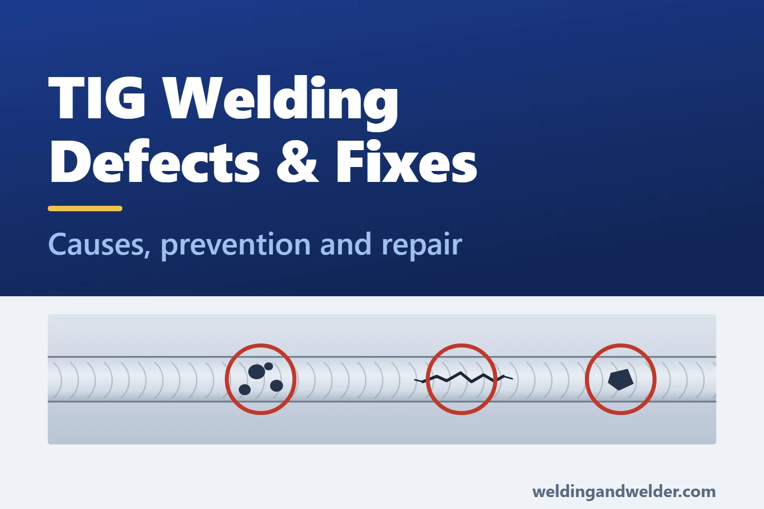
TIG welding, also called GTAW, gives the welder close control over the weld pool and any filler metal added. Making good use of that control depends on clean materials, suitable settings and an effective gas shield. When one of these is wrong, the result can be a weak, contaminated or poorly shaped weld.
This guide takes you through the common TIG welding problems, from recognising the signs and understanding possible causes to preventing them and choosing inspection methods that can find them. It covers porosity, cracks, poor fusion, tungsten inclusions, oxidation and the problems you may encounter with aluminium.
Browse our TIG welding supplies, including filler rods, tungsten electrodes, torches and gas accessories.
In this guide:
Start with the TIG Setup
Start by checking shielding, heat input, cleanliness, and the position of the torch and filler rod. Together, these give you a useful starting point for investigating many TIG problems. The joint design, filler and welding procedure also need to suit the material you are working with.
Four Checks to Make First
- Gas shielding. Start with the gas specified for the material, then set a suitable flow and check for leaks and draughts. Protection needs to continue after the arc stops, so keep gas flowing over the hot weld and tungsten.
- Heat input. Match current and travel speed so the required joint surfaces melt without overheating the part.
- Cleanliness. Remove oil, dirt, moisture and unwanted surface oxides from both the joint and filler, as TIG normally has no flux to help deal with contamination.
- Torch and filler position. Hold a short, steady arc, using a torch tilt of about 10 to 15 degrees from upright as a common starting point on flat joints. Feed filler into the front of the pool while keeping it clear of the tungsten.
Setting Shielding Gas Flow
Getting the gas flow right means providing enough protection without disturbing the shield. Too little can leave the weld exposed to air, while too much can create turbulence that draws air into it. The ranges below are approximate starting points for argon in sheltered conditions, with the actual flow depending on cup design, electrode stick-out and joint shape. Use the torch supplier’s guidance and test the setup to confirm what works.
| Application | Typical cup size | Argon flow: starting guide | Notes |
|---|---|---|---|
| General thin-sheet work | #4 to #6 | 5 to 8 L/min | Check coverage; a small cup does not need maximum flow |
| General steel and stainless work | #6 to #8 | 7 to 12 L/min | A suitable gas lens can improve coverage |
| Aluminium on AC | #6 to #8 | 8 to 12 L/min | Helium mixtures need settings and a flowmeter suitable for that gas |
| Titanium and other reactive metals | Cup and shielding system specified for the job | Set by the welding procedure | Torch, trailing shield and back purge may each need a separate controlled supply |
- Use the torch supplier’s starting flow. Set it while gas is running, using the supplier’s recommendation rather than cup number alone to establish the correct litres per minute.
- Use a suitable gas lens. Its screens even out the flow, which can improve coverage and allow more electrode stick-out. Confirm the coverage on your setup rather than assuming the lens alone provides it.
- Set enough post-flow. Post-flow keeps gas over the hot tungsten and weld after the arc stops. Around one second per 10 amps is a rough starting guide on some equipment; follow the machine instructions and allow enough time to protect both.
- Check the gas system. Work through hoses, seals and fittings using the supplier’s leak-checking method. Our gas regulators and flow control range covers the equipment.
TIG Welding Problems at a Glance
| Defect | Description | Possible causes | Prevention | Inspection options | Why it matters |
|---|---|---|---|---|---|
| Porosity | Gas pockets trapped in the weld | Poor gas coverage, draughts, contamination, moisture | Clean and dry the joint and filler; check gas flow and draughts | Visual for open pores; radiography or suitable ultrasonic testing for internal pores | Can weaken the weld or cause leaks |
| Cracking | Cracks in the weld or metal heated beside it | Depends on the crack type: alloy, filler, shrinkage, restraint or hydrogen | Use the correct filler and the specified heat control and joint preparation | Visual, penetrant or magnetic testing; suitable internal inspection where needed | Cracks can grow under load |
| Crater cracking | A crack in the depression at the end of a weld | The final weld pool contracts without enough metal to fill it | Reduce current gradually and fill the end of the weld | Visual, dye penetrant | A crack can extend into the weld |
| Lack of fusion | Weld metal has not fused to a joint surface or earlier weld pass | Insufficient heating, poor arc position, unsuitable preparation or oxides | Check current, travel, arc position, access and clean joint surfaces | Suitable ultrasonic testing; section or bend tests on samples | An unfused area can act like a crack |
| Lack of penetration | The weld does not reach the depth required by the design | Amps too low, root gap too tight, root face too large | Bring preparation and settings into line with the welding procedure | Root-side visual inspection; suitable radiography or ultrasonic testing | Reduces the effective joint section |
| Undercut | An unfilled groove beside the weld | Amps too high, arc too long, insufficient filler | Balance current, arc length, travel speed and filler feed | Visual, profile gauge | Creates a notch and reduces local thickness |
| Tungsten inclusion | Tungsten fragment trapped in the weld | Dipping the tungsten, touching it with the filler, overheating | Keep the tip clear and use the correct electrode size and preparation | Radiography; exposed fragments may be visible | Foreign metal interrupts the weld |
| Heat tint | Coloured oxide on the weld and surrounding metal | Insufficient shielding, excessive heat, short post-flow | Check shielding, heat input and protection during cooling | Visual assessment against the specified limits | Can reduce stainless steel’s corrosion resistance |
| Sugaring | Heavy, rough oxidation on a stainless weld root | Air reaches the hot root because backing protection is inadequate | Use the specified purge gas, oxygen limit and protection time | Root-side inspection, using a borescope where needed | Can affect corrosion resistance, cleanliness and weld quality |
| Distortion | The part moves out of shape | Excessive or unbalanced heat input, poor sequence | Control heat input, tack and support the part, and plan the weld sequence | Visual, measurement against drawing | Can put dimensions outside tolerance |
| Electrode deterioration | The electrode wears, splits or becomes contaminated | Wrong type or size, poor grinding, overheating, short post-flow | Use the specified electrode, preparation and gas protection | Inspect the tip and investigate an unstable arc | Can cause an unstable arc or contaminate the weld |
| Arc strikes | Stray arc marks on the parent metal | Striking outside the joint, careless torch handling | Start inside the prepared joint or on an approved run-on tab | Visual and suitable surface crack testing | Can leave local hard spots or cracks in susceptible materials |
Porosity: Gas Pockets in the Weld
Porosity means gas pockets have become trapped as the weld metal hardens. You may see some as pinholes on the surface, while others remain hidden inside. Whether they reduce strength or cause leaks depends on their size, number and position, so assess the weld against the acceptance limits for the job.
What Causes Porosity
- Dirty metal. Oil, grease, paint, rust, scale and cutting fluid can contaminate the pool or supply gas that becomes trapped.
- Dirty filler rods. Oil or moisture can be carried into the weld from the rods, hands or gloves, so keep rods clean and dry and use clean gloves when handling them.
- Moisture. This includes condensation on cold metal brought into a warmer workshop.
- Poor gas shielding. Check for excessive or insufficient flow, leaks, damaged torch seals or cups, and air movement across the joint.
- An overly long arc. It can leave the pool outside effective gas coverage and make the arc harder to control.
How to Prevent It
- Degrease, then remove unwanted oxides. Apply a suitable pre-weld cleaner and let it dry fully before abrading, as abrasion on a greasy surface can spread contamination. Keep brushes and abrasives separate for stainless steel and aluminium.
- Keep filler rods clean and dry. Use suitable closed storage and the rod supplier’s instructions. If you are considering a quiver, establish whether it is intended for bare TIG rods or coated electrodes. Cutting off one end of a contaminated rod does not clean the rest of it.
- Check gas flow and coverage. Begin with the table as a guide, then assess the actual torch setup. Simply increasing the gas flow will not automatically solve porosity.
- Protect the gas shield from draughts. Position screens and fume extraction to control exposure while keeping the shielding gas undisturbed.
- Check for leaks and the correct gas. If porosity continues after preparation has been checked, work through the torch, hose connections and gas supply.
Browse TIG welding rods and torch spares and consumables.
Cracks in TIG Welds
Because cracks can grow under load and lead to joint failure, the first step is to understand which type you are dealing with. Changing the heat or filler without identifying the cause can make the problem worse.
Cracking as the Weld Solidifies
Solidification cracking develops as the weld hardens and the partly solid metal contracts, pulling apart weak areas between its grains. This is why the cracks often appear along the centre of the weld or in the final crater.
- Susceptibility depends on the alloy and weld composition. This type of cracking can affect aluminium, austenitic stainless steels and nickel alloys.
- Deep, narrow welds and heavy restraint can increase the risk, so use the weld shape and sequence specified for the joint.
- For many austenitic stainless steels, a correctly selected filler helps resist cracking by leaving some ferrite in the weld. The required filler and ferrite level depend on the steel and service conditions, which means 308L and 316L cannot be treated as interchangeable choices.
Hydrogen Cracking (Cold Cracking)
Hydrogen cracking can occur in steels that harden during welding when hydrogen, a susceptible metal structure and tensile stress are all present. The cracks may develop as the joint cools or appear later. Although TIG usually introduces little hydrogen, moisture and other contamination still need attention.
- Use the preheat and temperature limits specified for the steel, joint thickness, restraint and welding conditions.
- Keep the joint and filler free from moisture, oil, paint and other sources of hydrogen.
- Follow the specified heat input, cooling and any post-weld heating requirements, as slower cooling is not a universal remedy for every joint.
Crater Cracking
The depression left at the end of a weld can also develop a crack. The next section explains how to fill this area and reduce that risk.
Prevention and Detection
- Choose the filler for the identified material and service. Our TIG Rod Finder and TIG filler rod guide can help you compare suitable choices, with the specified filler taking precedence where a welding procedure applies.
- Check joint design and restraint. The fit-up, weld shape and firmness of the restraint all affect shrinkage stress. If you want to change a specified joint, agree the change before welding.
- Use suitable inspection. Visual and penetrant testing can reveal surface cracks, while magnetic particle testing is suitable for ferromagnetic metals. Internal cracks need an appropriate ultrasonic or radiographic technique, because crack direction and material affect what can be detected.
Craters and Cracks at the End of a Weld
A crater is a hollow left at the end of a weld as the final pool cools and shrinks. If the hollow is not filled properly, the joint can be left with too little weld metal or may develop cracks. A crater will not always crack, but any crack that is found must be assessed and repaired as required.
Causes
- Stopping the current suddenly while the pool is still large.
- Too little filler at the finish to replace the volume lost as the metal shrinks.
- Current reduced too quickly by the pedal or the machine’s end-of-weld settings.
- A material prone to solidification cracking, combined with an unsuitable weld-end technique.
Prevention
- Reduce current gradually. Depending on the equipment, you can use a downslope or crater-fill function, or taper the current with a suitable foot pedal. Check which of these controls your TIG welding machine provides.
- Fill the final depression. Where the procedure permits it, moving slightly back over the bead and adding enough filler can leave the required profile at the finish.
- Coordinate filler and current. As the pool gets smaller, continue adding filler as needed to avoid finishing with a hollow or a large lump.
- Use run-off tabs where the design allows them, taking the crater outside the finished joint.
- Offset starts and stops between weld passes where the procedure calls for it.
Incomplete Fusion: Metal Has Not Joined Properly
Incomplete fusion means weld metal has not joined properly to a joint surface or an earlier weld pass. An unfused area can behave like a crack and may be hidden inside the joint, which makes the choice of inspection method important. Radiography can miss a tight, flat flaw, while ultrasonic testing needs a technique suited to the material and joint.
Causes
- Too little heat reaches the joint surfaces for them to melt properly.
- Travel is too fast for the chosen current and joint.
- Poor torch position or restricted access keeps the arc away from a side wall or the root.
- Too much filler before the joint has melted. Make sure the pool joins both surfaces before adding filler, as a bead sitting on top can conceal an unfused area beneath it.
- Unremoved oxides. An oxide can remain solid after the metal below it has melted; aluminium oxide, for example, stays solid at temperatures well above the underlying metal’s melting point.
How Thickness Changes the Setup
Choose current and filler size around the material, joint shape, position and individual weld pass. Thickness is only part of the decision: a root pass in thick plate may need much less current than the filling passes that follow. Start with a suitable procedure or the equipment supplier’s settings, then confirm the result on test pieces that match the work.
| Thickness | Steel: what to check | Stainless: what to check | Aluminium: what to check | Filler selection |
|---|---|---|---|---|
| 1 mm | Stable low-current starting and close control of the pool | Heat build-up, fit-up and distortion | Stable AC arc and quick current reduction as the sheet warms | A fine rod, if filler is required, that does not overwhelm the small pool |
| 2 mm | Current and travel speed that fuse both joint faces | Enough heat for fusion without lingering over the joint | Surface cleaning, AC balance and control of heat build-up | A rod that melts smoothly at the chosen current |
| 3 mm | Joint access, root preparation and required penetration | Root protection where required and control between passes | Adequate current, suitable electrode and torch capacity | Size for the pool and access, using the specified alloy |
| 6 mm | Whether a bevel and several passes are required | Separate settings for root and filling passes | Joint preparation, power available and any permitted preheat | A smaller rod may suit the root; later passes may use a larger one |
| 10 mm and over | A defined joint preparation and pass sequence | Required purge, heat input and interpass temperature limits | A procedure for the alloy; preheat is not automatic | Choose for each pass rather than total plate thickness |
Where the job requires a Welding Procedure Specification (WPS), this sets the permitted materials, preparation and welding conditions. Follow it and assess test welds against the applicable acceptance limits.
Incomplete Penetration: The Weld Is Too Shallow
Incomplete penetration means the weld has not reached the depth required by the joint design. Where the joint is intended to be welded right through, an unwelded root reduces the joined section and can leave a crevice. Check the drawing before judging the weld, though, because some joints are deliberately designed for partial penetration.
Before increasing the current, look at the joint preparation as well as the settings. The root face is the un-bevelled edge at the bottom of the joint; if it is too thick, the gap too narrow or access poor, the arc may not reach the root. More current alone may simply cause burn-through elsewhere.
- Possible causes: too little current, excessive travel speed, poor arc position, unsuitable root gap or bevel, or a filler rod too large for the root pool.
- Prevention: begin with fit-up against the procedure, then assess current, travel and filler size. Correct unsuitable preparation instead of trying to overcome it with excessive current.
- Use the specified root technique. Some open-root methods create a small keyhole ahead of the pool, but seeing one does not prove that penetration is acceptable. Other TIG root techniques do not use a keyhole at all.
- Check whether backing is appropriate. A suitable ceramic backing tape can support a single-sided weld where the procedure permits it, although the material may still require gas protection. Backing does not automatically replace that protection.
Undercut and Other Weld-Shape Problems
The weld profile describes its shape and size. Visual inspection and suitable gauges can reveal many profile problems, with the drawing or acceptance standard providing the limits to judge them against.
- Undercut is an unfilled groove at the weld edge that reduces local thickness and creates a notch where fatigue cracks may develop. To address it, consider current, arc length, travel speed and filler feed together, making adjustments within the procedure.
- Overlap occurs when weld metal extends over the surface without fusing to it, leaving a lip that adds no useful joint strength. Look for an oversized pool, excessive filler or poor control of heat and travel as possible causes.
- Excess reinforcement means the weld stands higher than permitted, and a steep transition into the plate can concentrate stress. Assess the height and shape together against the specified limits.
- Underfill leaves the weld surface below the required level and reduces the joint section, so check filler feed, travel speed and the finished dimensions.
- Arc strikes are accidental arc marks outside the intended weld, where rapid local heating and cooling can leave hard spots or cracks in susceptible metals. Report and treat them as the specification requires, and start the arc inside the prepared joint or on a permitted run-on tab.
Tungsten Fragments in the Weld
A tungsten inclusion is a piece of electrode trapped in the weld. It may come from the tip touching the pool or from an electrode that is damaged or overheated. Because tungsten absorbs X-rays strongly, radiography can detect these fragments, although their size and the inspection technique still affect how clearly they can be seen.
Causes
- Touching the pool with the tungsten, which contaminates the tip and may leave a fragment in the weld.
- Touching the electrode with the filler rod, which can contaminate or damage the tip.
- Exceeding the electrode’s capacity for its diameter, composition, tip shape and polarity.
- Using a damaged or poorly prepared electrode, which may split or shed material.
- Grinding around the electrode rather than along its length, which can contribute to an unstable arc.
Tungsten Diameter and Current: Example Ratings
| Tungsten diameter | Example current range: DCEN with argon | Typical application |
|---|---|---|
| 1.0 mm | 15 to 80 A | Thin sheet and precision work |
| 1.6 mm | 70 to 150 A | Light sheet-metal work |
| 2.4 mm | 150 to 200 A | General fabrication within the electrode rating |
| 3.2 mm | 250 to 400 A | Higher-current work with suitable equipment |
The example ranges below come from Miller’s Multimatic 220 manual and apply to 2% ceriated or 1.5% lanthanated electrodes used with argon and direct current electrode negative (DCEN). They are guides, rather than universal limits or a statement of that welder’s maximum output, so use the ratings for your own electrode and machine. AC capacity also depends on waveform and balance and is not necessarily lower than DC capacity.
Prevention
- Keep a short, steady arc. Supporting your hand where practical can help you maintain the clearance needed to keep the tungsten out of the pool.
- Feed filler into the front of the pool at a shallow angle, leaving enough clearance to keep the rod away from the tungsten.
- If the tip becomes contaminated, stop. Use suitable equipment to cut or grind away the affected section, then prepare the tip again. Snapping it off can split the electrode, so avoid doing that and assess the weld for trapped tungsten before continuing.
- Use a dedicated grinding setup. A suitable tungsten grinder makes it easier to produce a consistent tip without transferring contamination from other metals. The grinding dust also needs to be controlled.
Choosing and Maintaining the Tungsten
The tungsten carries the arc and should not be consumed as filler. If its tip becomes contaminated, split or overheated, the arc can become unstable and tungsten may be left in the weld. An unexpected change in the arc is therefore a reason to inspect the electrode.
Choosing the Right Electrode
- Lanthanated electrodes: gold WL15 or blue WL20. Suitable for many AC and DC applications, with the diameter and tip preparation chosen to match the machine and current recommendations.
- Ceriated electrodes: grey WC20. These can start reliably at low current, making them useful for many thin-sheet and precision applications.
- Zirconiated electrodes: white WZ8. These are used on suitable AC equipment, often with a rounded tip. For an inverter, follow its electrode recommendation rather than assuming that all AC machines need this type.
- Thoriated electrodes: red WT20. Although these perform well in many DC applications, they contain radioactive thorium oxide, so grinding dust needs suitable extraction, handling and disposal controls. Consider whether a suitable non-thoriated alternative would do the job, and follow the product safety data and workplace assessment.
- Pure tungsten: green WP. This is still used on some traditional AC equipment, while many modern inverters specify an alloyed electrode.
Grinding and Care
- Grind lengthwise. Use a setup that leaves the grinding marks running along the electrode and produces a smooth, consistent tip.
- Use the specified tip angle. A longer taper can help with low-current starting, while a blunter preparation can carry more current. Let the application determine the geometry rather than using one taper-length rule for every job.
- Add a small flat where specified. The recommended flat size can help the tip resist erosion and keep its shape, avoiding a fragile needle point.
- Keep the grinding wheel for tungsten only. A shared wheel can transfer steel or other metals to the electrode, so use a dedicated wheel and suitable dust controls.
- Protect the tip while it cools. If it darkens after the arc stops, investigate post-flow, the gas supply and torch seals before continuing.
Browse tungsten electrodes and tungsten grinders.
Oxidation and Heat Tint
Heat tint can reduce the corrosion resistance of stainless steel. The colour comes from an oxide film that forms while the surface is hot and can draw chromium from the metal beneath it, leaving that layer less resistant to corrosion. Heating time, temperature, surface finish and the atmosphere all affect the colour, so a generic chart cannot tell you whether every weld meets its acceptance limits.
Causes
- Poor gas coverage caused by unsuitable flow, cup size, electrode stick-out, leaks or draughts.
- A large or long-lasting hot area that stays exposed to air outside the gas shield.
- Insufficient protection during cooling, including post-flow that ends too soon or a torch moved away too quickly.
- Damaged or incorrectly assembled torch parts, such as a cracked cup, faulty seal or damaged gas lens.
Prevention and Remedy
- Check the whole shielding setup. A suitable gas lens can improve coverage, but leaks, draughts and unsuitable torch positions still need to be corrected.
- Control heat input. Balance current with travel speed so fusion is maintained. Suitable pulse settings may help, although using pulse does not automatically mean heat input will be lower.
- Maintain gas protection after stopping. Leave the torch over the finishing area for the required post-flow time, adding trailing or backing protection where the procedure calls for it.
- Use the specified cleaning process. Where corrosion resistance requires it, remove both the oxide and the affected metal beneath it using a suitable mechanical, chemical or electrochemical method. Passivation helps a protective film form and removes certain surface contaminants, but it cannot remove heavy oxide or replace lost chromium. Any chemical treatment must be used according to its handling and safety instructions.
Sugaring: Heavy Oxidation Behind the Weld
Sugaring is heavy, rough oxidation on the underside of a stainless steel weld. It develops when air reaches the root while the metal is molten or very hot. A back purge supplies a suitable gas to protect this area during both welding and cooling.
The concern with this rough oxide is that it can reduce corrosion resistance and leave a surface that is difficult to clean, particularly inside process or hygienic pipework. Use the repair and acceptance requirements to assess it, as severe or inaccessible damage may mean cutting out the joint. Titanium also needs protection from air while hot, although its surface colour alone cannot establish how much contamination is present.
Causes
- No suitable backing protection where the material and joint require it.
- Protection stopped too soon. The root can still oxidise after the arc stops or during later passes if protection ends too soon.
- Too much oxygen remains at the start because the joint was not adequately purged.
- Air leaks into the purge space through poor seals or an unsuitable setup.
- Excess purge pressure, which can distort the molten root. Poor venting can make pressure build up.
Prevention
- Establish the purge before welding. Use the specified gas and a setup that displaces air from the root area, allowing for the way the space, flow and gas mixing affect purge time.
- Measure oxygen where required. A suitable calibrated analyser lets you check against the limit specified for the alloy, service and welding procedure. The same oxygen limit cannot be applied to all stainless or titanium work.
- Reduce the space that needs purging. Suitable dams can isolate the area around the joint, avoiding the need to fill a whole pipe run.
- Keep protection in place for the required passes and cooling period. Use the procedure’s temperature or timing criteria to determine how long it is needed.
- Provide controlled flow and an outlet. Keep purge pressure within the procedure’s limits and include the discharge in the workplace ventilation assessment, because purge gases can displace breathable air.
See our guide to welding purging for more on purge equipment and setup.
Distortion: Keeping the Part in Shape
Distortion happens when uneven heating and cooling pull the part out of shape. Thin sheet is especially vulnerable, while austenitic stainless steel generally expands more and conducts heat less readily than carbon steel. These characteristics make heat control and weld sequence important parts of keeping the finished component in shape.
Causes and Prevention
- Control heat per length of weld. Use enough current to achieve fusion and travel steadily. Lowering current can make you move more slowly and put more heat into the part, while pulse settings only help when chosen to suit the joint.
- Plan a balanced sequence. Where the design permits it, choose an order that spreads the heat and shrinkage across the part.
- Limit heat build-up. Use short runs, back-step or skip sequences where permitted, keeping the temperature between passes within the specified limits.
- Support and align the parts. Suitable pipe alignment clamps or jigs help hold the fit-up, but the fixture needs to suit the job because excessive restraint can increase stress.
- Use suitable tack welds. Their size and spacing need to hold the fit-up without introducing unacceptable defects. Where tacks will form part of the finished weld, prepare them as the procedure requires.
- Use backing where appropriate. A suitable clean copper backing bar can support thin sheet and remove heat, provided the procedure permits it. Take care to avoid melting copper into the weld.
- Allow for predictable movement. Where approved, parts can be set slightly out of line before welding so the expected shrinkage brings them into the required position.
| Material thickness | Common concern | Useful controls |
|---|---|---|
| Under 2 mm sheet | Burn-through and buckling | Close fit-up, suitable tacks, controlled travel and permitted backing |
| 2 to 6 mm plate | Angular distortion and loss of alignment | Planned weld sequence, suitable support and controlled heat input |
| Over 6 mm plate | Shrinkage, residual stress and distortion across several passes | Specified pass sequence, balanced welding and interpass temperature control |
TIG Welding Aluminium: Problems and Checks
With aluminium, you are welding a metal with a relatively low melting temperature beneath a tough oxide film. Pure aluminium melts at about 660 degrees Celsius, while its alloys melt over ranges determined by their composition; aluminium oxide melts above 2,000 degrees Celsius. The surface needs cleaning before welding. During AC TIG welding, the electrode-positive part of the cycle helps break up the oxide, but also puts heat into the tungsten.
| Problem | Possible causes | What to check |
|---|---|---|
| Black soot or grey dust around the weld | Contamination, poor shielding, or deposits associated with the alloy and filler | Work through surface and filler cleanliness, tungsten condition and gas coverage before deciding whether AC cleaning is involved. Black deposits alone do not prove that cleaning is too low |
| Weld looks dirty and will not wet out | Remaining oxide, contamination, or insufficient heating or AC cleaning | Degrease first, then remove oxide with a dedicated suitable brush or abrasive and weld promptly. Adjust AC balance only as needed, using the machine’s definition of EN and EP |
| Tungsten balls excessively or spits | Overloaded electrode, too much electrode-positive time, or unsuitable tip preparation | Start with the electrode type, size and current rating. Follow the machine instructions to reduce excessive EP time while retaining enough cleaning |
| Porosity throughout the weld | Hydrogen, usually from moisture, oil or hydrated oxide | Clean and dry the joint and filler; remove hydrated oxide and check gas-system leaks |
| The pool suddenly collapses | Heat build-up, excessive current, poor fit-up or inadequate support | Use the pool’s size and shape to guide any current reduction, with permitted backing where needed. Aluminium gives little visible colour warning before melting |
| Crater cracks at every stop | Shrinkage of an inadequately filled crater, with alloy and filler also affecting cracking | Use the specified filler, reduce current smoothly and fill the final crater |
Our aluminium TIG filler rod range includes 4043 and 5356, with the choice of filler depending on the alloy and service requirements.
Arc Starting and Machine Problems
When an arc will not start or stay steady, investigate the setup before changing your welding technique. Use the possible causes in the table alongside the machine’s fault information and manual to narrow down the problem. Isolate equipment before maintenance and leave internal electrical work to competent service personnel.
| Symptom | Possible causes | Check |
|---|---|---|
| No arc at all | Poor work-return connection, incorrect mode, trigger or remote-control problem, or a machine fault | Check the work-return clamp, plugs, selected TIG mode, remote settings and displayed fault code |
| High-frequency spark but no welding arc | Excessive arc gap, poor work-return contact, contaminated tip or output/start fault | Check return contact, the specified starting gap, tip condition and machine fault information |
| Arc starts then dies | Unsuitable start/current settings, intermittent return contact, remote control or protection fault | Work through the start sequence, current setting, connections and fault indications, while also confirming that shielding gas is flowing |
| Arc wanders or splits in two | Contaminated or split tip, unsuitable preparation or current, or magnetic arc deflection on DC | Inspect and prepare the tip and confirm that the electrode suits the current. If the problem remains, investigate magnetic effects |
| Arc is harsh and erratic on AC | Unsuitable balance, frequency or waveform settings; damaged electrode or torch parts | Start with the manufacturer’s recommended settings, then check the electrode and torch assembly |
| Tungsten oxidises the moment you stop | Insufficient post-flow, lost shielding gas or a torch leak | Check the gas supply, seals and post-flow time, keeping the torch in place while the tip cools |
| Machine cutting out mid-weld | Overheating, cooling or supply fault, or another protective shutdown | Read the fault code and manual, then check the duty rating and carry out only the permitted cooling checks. Let the machine cool as instructed and never bypass its protection |
Torch parts affect both current delivery and gas coverage, so damage or incorrect assembly can look like a technique problem. Check the collet, seals, cup and gas lens as part of the investigation. You can browse replacements in our TIG torch spares and consumables range.
TIG Repair Welding
TIG can be useful for repairs that need carefully placed weld metal. Where the material and approved repair method allow, it can rebuild worn areas, fill prepared damage or restore dimensions. A valuable component still needs to be suitable for welding; its value alone does not establish that.
Begin by identifying the material and confirming that welding is an approved repair. A typical repair then involves removing the damaged material, checking the prepared area and rebuilding it in controlled passes before restoring the required shape. The repair procedure determines the inspection and any heat treatment needed.
- Remove and check the damaged area. Follow the specified preparation and inspection method to confirm that unacceptable cracks or other damage have been removed. Penetrant testing can find surface-breaking flaws, while magnetic particle testing needs a ferromagnetic material.
- Identify the material before choosing filler. Whether the repair can work depends on the alloy composition, heat treatment and service conditions.
- Follow the repair’s heat limits. Control preheat, heat input and the temperature between passes, and use the specified bead size and sequence. Very low current or long cooling pauses are not automatically the best approach.
- Check heat-treatment requirements. Some materials or repair specifications require preheat, post-weld heat treatment or both.
- Inspect against the applicable repair requirements. Use the tests and acceptance limits determined by the component’s code, owner or manufacturer. Do not assume that a repair simply calls for a stricter version of the original inspection.
Inspecting TIG Welds and Applying Acceptance Limits
An imperfection becomes unacceptable when it exceeds the limits for the job, so start with the drawing, contract and applicable fabrication or repair specification. These establish both the acceptance limits and the inspection required. Common references include:
- BS EN ISO 6520-1 classifies and numbers weld imperfections in fusion welding.
- BS EN ISO 5817 gives quality levels B, C and D for fusion welds in steel, nickel, titanium and their alloys, excluding beam welding. B is the most stringent. For arc-welded aluminium and its alloys, BS EN ISO 10042 sets quality levels for imperfections. Use the standard and level specified for the job; a quality level alone does not establish fitness for every service.
The right inspection method depends on the material, joint, access and faults you need to find. Each method has limits, and no single one finds every imperfection:
| Method | What it can find | Main limits |
|---|---|---|
| Visual (VT) | Visible profile faults, undercut, oxidation, open pores, some cracks and arc strikes | Requires access and suitable lighting, and cannot establish the condition inside the weld |
| Dye penetrant (PT) | Cracks and other flaws open to the surface | Works on suitable clean, non-porous surfaces, including many non-magnetic metals, but cannot reveal sealed internal flaws |
| Magnetic particle (MT) | Surface and near-surface cracks | For ferromagnetic metals; not suitable for austenitic stainless steel, aluminium or titanium |
| Ultrasonic (UT) | Internal flaws, including many cracks and unfused areas | Detection depends on material, thickness, flaw direction, access and the chosen technique |
| Radiography (RT) | Gas pores, tungsten inclusions and some incomplete-penetration flaws | Tungsten can produce strong contrast, while tight cracks and unfused areas may be missed if their direction is unfavourable |
TIG Welding Questions
What is sugaring in TIG welding?
Sugaring is the heavy, rough oxidation that develops on the underside of a stainless steel weld when air reaches the hot root. Preventing it means using the backing gas, oxygen limit and protection time required by the welding procedure. If a weld is affected, assess it against the job requirements: cleaning or an approved repair may be possible, while severe or inaccessible damage may require the joint to be removed.
Why is my TIG weld turning blue, grey or black?
On stainless steel, these colours usually mean the surface oxidised while the weld was hot. Work through gas coverage, leaks, draughts, heat input and protection during cooling to find the cause. Several conditions affect colour, so silver, straw or blue cannot give a universal pass or fail result. Apply the specified acceptance and cleaning requirements, remembering that passivation alone does not remove heavy heat tint or the affected metal beneath it.
What causes tungsten inclusions?
Fragments can enter the weld when the tungsten touches the pool or filler, overheats, or breaks down because the tip is damaged. If the electrode becomes contaminated, stop and cut or grind away the affected section using suitable equipment, then prepare the tip as specified. Before continuing, check the weld for any trapped tungsten.
What gas flow rate should I use for TIG welding?
Begin with the flow recommended for your torch, cup, gas and joint. For general steel or stainless work using a number 6 to 8 cup in sheltered conditions, around 7 to 12 litres per minute of argon can be a starting range, with coverage confirmed on test pieces. Cup number alone cannot determine the flow, and too much gas can draw air into the shield, so investigate leaks and draughts before turning it up.
What is the correct arc length for TIG welding?
Aim for a short, steady arc that keeps the tungsten clear of the pool. Around 1 to 3 mm is a common starting range for many manual TIG jobs, with the actual gap depending on current, joint shape, electrode preparation and the technique required. Use the equipment or procedure guidance rather than treating electrode diameter as a fixed rule for arc length.
What can TIG repair welding fix?
Where an approved repair is possible, TIG can rebuild local wear, restore dimensions or weld an area prepared to remove a crack or other damage. Whether it is suitable depends on the alloy, condition and service requirements. Identify the material, remove and inspect the damaged area, then follow the specified filler, heat control and final inspection requirements. Using TIG does not automatically mean the repair will have low heat input or low distortion.
Why does my TIG arc wander or split?
Start with the tungsten, looking for contamination, splitting or unsuitable tip preparation and checking that its size suits the current. Then work through the work-return connection, shielding and machine settings. If these are sound, magnetic fields may be deflecting a DC arc, so investigate the return path and any magnetism in the part. Moving the clamp may help in some cases.
Why is my aluminium TIG weld black and sooty?
Black deposits may come from contamination, poor shielding or alloying elements in the base metal and filler, so they do not automatically mean AC cleaning is too low. First check that the joint and filler are clean and dry, the tungsten is in good condition and gas coverage is effective. If oxide remains in the pool, review AC balance using the machine instructions: more electrode-positive time increases cleaning but also heats the tungsten.
A Practical TIG Quality Check
A practical quality check begins with a suitable joint and welding procedure, followed by checks of material preparation, shielding, heat input and electrode condition. If a fault appears, work out what is causing it, make a controlled change and test the result before continuing production.
- Cleanliness. Keep the joint, filler and tungsten free from unwanted oil, moisture and contamination.
- Shielding. Check the gas, flow, torch condition and protection of both the weld face and root where required.
- Heat control. Balance current and travel speed to achieve the required fusion and profile within the procedure’s limits.
- Electrode condition. Use the correct type, diameter and tip preparation. Stop and investigate if the electrode becomes damaged or contaminated.
TIG Equipment and Consumables
👉 TIG welding supplies · TIG filler rods · Tungsten electrodes · Tungsten grinders · Torch spares · TIG welders
You can also find related guidance in our articles on common MMA welding problems, TIG filler rods and AWS codes and welding positions.